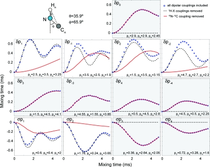
Figure 3.
Heteronuclear polarization transfer for the PAIN-CP conditions highlighted in the text. Simulations with all the dipolar couplings included (blue circle), and 1H–X (black dashed line) or 15N–13C (red solid line) couplings removed are considered. The spin system (top left) consists of three spin and the magnetization starts on the nitrogen and is detected on the carbon. The simulations include typical anisotropic chemical shift interactions (see Sec. 2C). The rf power levels of the three CW irradiations are chosen based on optimization maps (indicated by stars on Fig. SI 2–5) (Ref. 26) and correspond to settings resulting in adequate polarization transfer efficiency. The rf power level settings (in units of the MAS frequency) are shown directly on the figure. The panels with the grey and with the white background indicate respectively conditions without and with concurrent 15N–13C CP active during the experiment.

