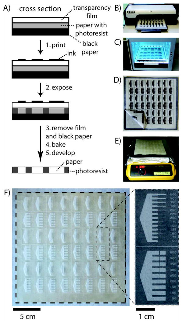
Fig. 1.

Procedure for FLASH fabrication of microfluidic devices in paper. (A) Schematic of the method. (B) Designs for microfluidic channels were printed directly onto FLASH paper (the paper is Whatman Chromatography paper No. 1). (C) FLASH paper was exposed to UV light. (D) The photoresist-impregnated paper was removed from the transparency film and black construction paper. (E) The paper was baked on a hotplate. (F) After developing the paper in acetone and 70% isopropyl alcohol, the microfluidic devices are ready for use. The dotted lines indicate the edges of the paper.
