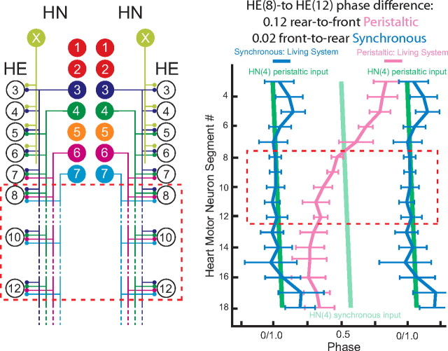
Figure 1.
Connections from the heart interneurons of the leech heartbeat CPG onto motor neurons in the first 12 midbody segmental ganglia and the bilateral output pattern of heart motor neurons. Left, Bilateral circuit diagram including all the HN interneurons of the CPG [identified HN(3), HN(4), HN(6), HN(7) and unidentified HN(X)] and their pattern of synaptic connections to HE motor neurons in HE(3)–HE(12). Large colored circles are cell bodies and associated input processes. Lines indicate cell processes, and small colored/black circles indicate inhibitory chemical synapses. Standard colors for the identified interneurons are used (for color code, see Materials and Method), e.g., lime green is used for the X interneuron. Right, Simplified composite phase diagram showing the average ± SD phase of heart motor neuron output in the living system for both peristaltic and synchronous coordination. Data are replotted from Norris et al. (2007b) and represent averages from n = 61 different preparations. The bilateral absolute phase of each segmental motor neuron with the peristaltic HN(4) interneuron as the phase reference is shown. Two synchronous (blue) and one peristaltic (pink) phase curves are shown. The phase of the peristaltic HN(4) interneuron is indicated with a slanted green straight line, and the phase the corresponding synchronous HN(4) interneuron is indicated with a slanted light green straight line. The slopes of these lines reflect the conduction delays from segment to segment. In this study, we focused on the HE(8)–HE(12) motor neurons, and their representations are bordered by a red dashed line in each panel.

