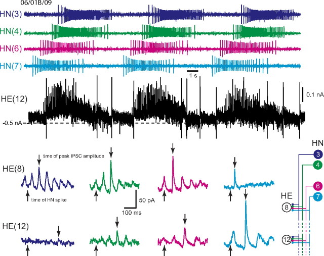
Figure 3.
Determining the absolute and relative synaptic strength of each input to a heart motor neuron. In the top, an HE(12) motor neuron was recorded in voltage clamp (holding potential, −45 mV) simultaneously with extracellular recording from four ipsilateral premotor heart interneurons, HN(3), HN(4), HN(6), and HN(7). HN spikes from 11 bursts (including the ones illustrated) from each interneuron were used to generate the spike-triggered averages of IPSCs in the HE(12) motor neuron, and subsequently similar recordings were used to generate the spike-triggered averages of IPSCs for the HE(8) motor neuron in the same preparation. Upward arrows indicate the time of the triggering HN spike, and the downward arrows indicate the peak of the averaged IPSC used to measure amplitude: standard colors identify each heart interneuron and associated spike-triggered average IPSC. Iconic unilateral circuit diagram (bottom right) identifies the recorded neurons. Preparations are specified by the day on which they were recorded: letters accompany the day designation if more than one preparation was recorded on that day.

