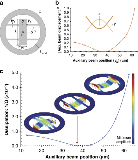
Figure 1. Mapping out phonon-tunnelling dissipation in a free–free resonator.
(a) Schematic diagram of the resonator geometry. (b) Normalized squared centre of mass displacement of a single auxiliary-beam central-resonator contact calculated via FEM (the inset shows the profile of the free–free mode as approximated by Euler–Bernoulli theory). (c) Simulated dissipation (see equation (2)) as a function of the auxiliary beam's y-coordinate (ya). Values corresponding to eight discrete geometries were calculated here with t=6.67 μm, ws=7 μm, w=42 μm, L=132 μm, R=116 μm and Lund=27 μm—the line is simply a guide for the eye. The FEM-calculated mode shapes correspond to the three extreme examples of the resonator design, from left to right: auxiliary beams near the resonator centre (ya=13 μm), beams near the ideal nodal position (ya=37.4 μm) and beams attached at the ends (ya=62.5 μm). The theoretical clamping loss limit 1/Qth for nodal positioning is always finite with the geometry closest to this position (indicated by the arrow) yielding 1/Qth≈2×10−7.

