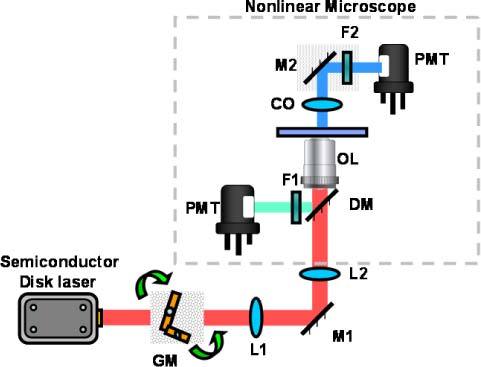
Fig. 1.

Schematic experimental setup used for nonlinear imaging. The red path corresponds to the fundamental excitation beam centered at 965nm, the blue path to the SHG emission and the green path to the TPEF emission. L# are lenses; GM are the galvanometric mirrors; OL is the objective lens (40x, NA = 1.3), CO is the condenser optics (NA = 1.4); F1 ad F2 are the band pass filters (F1 transmittance = 330 – 670 nm and F2 transmittance = 475 – 485 nm); and PMT are the photo multiplier tubes.
