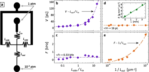
Figure 3.
Drop properties can be controlled using resistor channels. The resistors are placed on the inlets of the drop maker at the locations indicated in (a). The resistors enable the flow rates of the inner and continuous phases to be controlled. By varying the length ratio of the inlet resistors, we control the flow rate ratio in the drop maker. This allows the drop volume to be controlled, as shown by drop volume plotted as a function of inlet resistor length ratio in (b); varying this ratio does not significantly affect the drop formation frequency, as shown in (c). By varying the length of the outlet resistor, we control the total flow rate through the device; this allows us to form drops of constant volume, but at a different formation frequency, as shown by the plots of volume and frequency as a function of the inverse of the outlet resistor length in (d) and (e), respectively. The measured hydrodynamic resistance of a resistor channel with water as a function of length is shown as inset into (d) (enhanced online).

