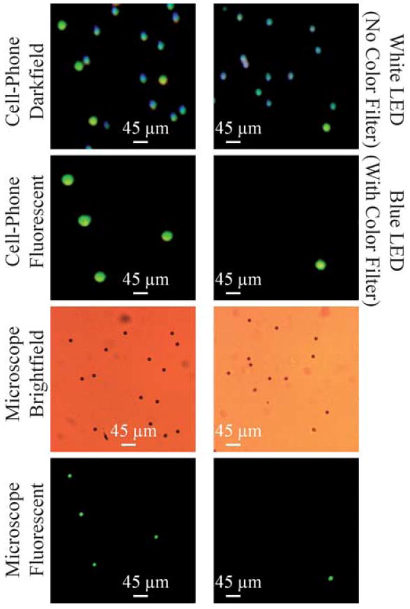
Fig. 7.

Darkfield imaging capability of our cell-phone microscope (Fig. 1) is demonstrated using a mixture of fluorescent and non-fluorescent 10 μm beads. (Top row) Darkfield images of two different zoomed regions of the sample are illustrated. Because the illumination was achieved using a white LED (without any color filter in front of the sensor), the scattered light from non-fluorescent beads creates their darkfield images. The fluorescent beads can still be excited using this white LED and therefore their green fluorescent emission is also visible in this darkfield image. (Second row) Fluorescent images of the same FOV are illustrated using the cell-phone microscope. The illumination was achieved using a blue LED which efficiently pumped the green fluorescent beads as evident in their images. The non-fluorescent beads do not show up in this image since a color filter in front of the cell-phone sensor rejected the pump wavelength. (Third row) Conventional bright-field microscope images of the same FOV are illustrated using a 10× objective lens for comparison purposes. (Bottom row) Conventional fluorescent microscope images of the same FOV are illustrated using a 10× objective lens for comparison purposes. Note also that because the samples were suspended in a solution, their relative orientations might be slightly shifted in their microscope comparison images.
