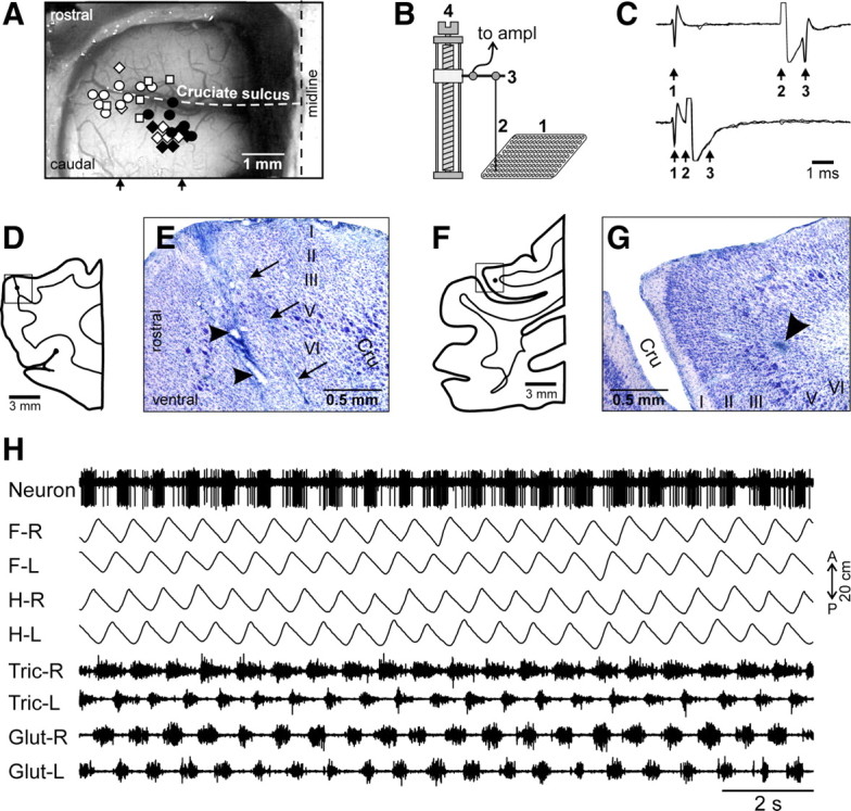
Figure 2.

Areas of the motor cortex studied. A, Areas of recording within representations of the forelimb and hindlimb in the left motor cortex. Microelectrode entry points are combined from cats 1 (circles), 2 (diamonds), and 3 (squares) and shown by white (forelimb-related neurons in the track) or black (hindlimb-related neurons in the track) symbols on a photograph of cat 2 cortex. Arrows indicate approximate mediolateral positions of parasagittal sections shown in D–G. B, The method of insertion and advancement of electrodes into cortex. A microelectrode (2) is manually inserted into one of the openings in the plastic plate (1) implanted into the skull and is then soldered to an arm (3) of a micromanipulator (4). In this manually driven micromanipulator, one revolution of the screw results in 200 μm advancement of the electrode. C, Collision test determines whether a PTN response is antidromic. Top trace, A PTN spontaneously discharges (arrow 1), and pyramidal tract neuron is stimulated ∼5 ms later (arrow 2). PTN responds with a latency ∼1 ms (arrow 3). Bottom trace, A PTN spontaneously discharges (arrow 1) and pyramidal tract is stimulated ∼0.5 ms later (arrow 2). The PTN does not respond (arrow 3) because in 0.5 ms its spontaneous spike was still en route to pyramidal tract, and thus collision/nullification of spontaneous and evoked spikes occurred. D, Drawing of a parasagittal section through the rostral bank of the cruciate sulcus (Cru). The reference track made with a thick electrode is shown by a tilted line and the position of the reference electrolytic lesion is shown by a black circle. The square approximately indicates the area shown in the photomicrograph in E. E, Photomicrograph of a parasagittal section through the motor cortex, stained with cresyl violet. Layers of the cortex are numbered. Clusters of giant cells in layer V that are characteristic for area 4γ are visible around the lesion. Arrows point to a track made by a microelectrode. Arrowheads point to the reference electrolytic lesions. F, Drawing of a parasagittal section through the caudal bank of the cruciate sulcus. The position of the reference electrolytic lesion is shown by a black circle. The square approximately indicates the area shown in the photomicrograph in G. G, Photomicrograph of a parasagittal section through the motor cortex, stained with cresyl violet. Layers of the cortex are numbered. An arrowhead points to the reference electrolytic lesion. Clusters of giant cells in layer V that are characteristic for area 4γ are visible around the lesion. Scales in D–G were not corrected for shrinkage of tissue during processing. H, An example recording of a neuron along with four movement sensors for four limbs (F-R, right forelimb; F-L, left forelimb; H-R, right hindlimb; H-L, left hindlimb) and four muscles (Tric-R, right triceps; Tric-L, left triceps; Glut-R, right gluteus; Glut-L, left gluteus) during quadrupedal locomotion.
