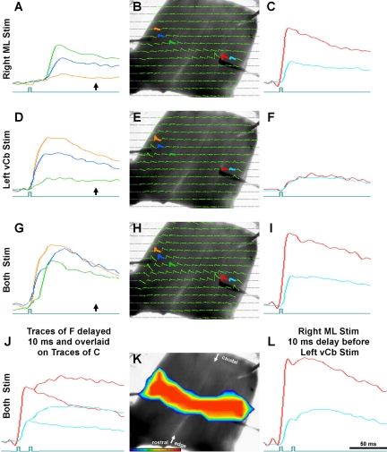
Fig. 6.
Conjoint Cb microstimulation into both medial ML (A–C) and lateral edge (vCb; D–F) using the same Cb shown in Fig. 5. Third and fourth rows show responses to simultaneous stimulation of both (G–L). A shows superposed traces of 3 diodes in the left Cb hemisphere (marked in B), far from the ML stimulation site. Onset times of all these traces are much delayed and the orange trace barely responds as it is in the contralateral vCb. C: superimposed traces of 2 diodes in the right Cb hemisphere, close to the ML stimulation site. Onset of the blue trace is slightly delayed as it is to the right of the stimulation. D and F: responses of vCb microstimulation, using the same diodes as A and C, respectively. Onset times of these traces are very similar. During both stimulation of the ML and vCb, the traces in G have 2 components, a short latency response (due to vCb stimulation) and a delayed response (due to the distant ML stimulation). Unlike I, which shows responses to simultaneous stimulation, L shows responses when the vCb stimulation was delayed by 10 ms relative to the ML stimulation. Both the red and blue traces of L exhibit an early and late response component. These 2 components compare well to the shapes of the overlaid traces of C and F shown in J. See description in text. Arrows below the traces in B, F, and J show the time point to which pseudocolor frames of Fig. 5, C and D, and Fig. 6K correspond, respectively.

