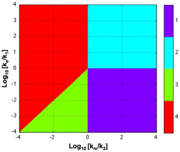
FIGURE 2.

System design space for the model in Fig. 1. Case 1 (Purple): the same dominant flux into pool 1, between pool 1 and pool 2, and from pool 2 by metabolism. Case 2 (Blue): a dominant flux into pool 1 and from pool 1 by excretion; a second dominant flux into pool 2 and from pool 2 by metabolism. Case 3 (Green): rapid quasi-equilibrium between pools 1 and 2; an influx to pool 1 and an equivalent efflux from pool 2. Case 4 (Red): rapid quasi-equilibrium between pools 1 and 2; an influx to pool 1 and an equivalent efflux from pool 1 by excretion. See Fig. 3 and text for discussion.
