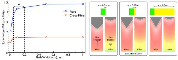
Fig. 6.
Variation in conduction velocity ratio of the BDM case relative to the BDMNB case as the width of the bath is varied for propagation along both the fibre (blue) and cross-fibre (red) directions (using Roberts & Scher (1982) conductivities). Panels on right show snap-shots of Vm distributions within the slab model for 3 different bath widths, each showing both the case of propagation along the fibre (left) and the cross-fibre (right) directions, at the time instances given at the base of each image.

