Abstract
While interfacial graphite formation and subsequent poor film adhesion is commonly reported for chemical vapor deposited hard carbon films on cobalt-based materials, we find the presence of O2 in the feedgas mixture to be useful in achieving adhesion on a CoCrMo alloy. Nucleation studies of surface structure before formation of fully coalesced hard carbon films reveal that O2 feedgas helps mask the catalytic effect of cobalt with carbon through early formation of chromium oxides and carbides. The chromium oxides, in particular, act as a diffusion barrier to cobalt, minimizing its migration to the surface where it would otherwise interact deleteriously with carbon to form graphite. When O2 is not used, graphitic soot forms and films delaminate readily upon cooling to room temperature. Continuous 1 μm-thick nanostructured carbon films grown with O2 remain adhered with measured hardness of 60 GPa and show stable, non-catastrophic circumferential micro-cracks near the edges of indent craters made using Rockwell indentation.
1 Introduction
Cobalt–chromium alloys are widely used as the bearing surfaces in orthopedic implants such as needed in total hip and knee replacement surgeries because of their superior mechanical properties and resistance to corrosion and biodegradation [1]. According to the American Academy of Orthopaedic Surgeons, the number of total knee replacements and total hip replacements performed in the U.S. will leap by 673 and 174%, respectively, by the year 2030 [2]. Despite improvements in surgical technique and in the designs of prostheses, revision rates do not seem to be declining over time. Wear of articulating surfaces involving Co–Cr–Mo alloy-on-polyethylene (used in the majority of hip and knee arthroplasties) has been cited as a dominant factor limiting the long-term success of the implant [3, 4]. Orthopaedic research [5–7] has revealed that much less wear occurs with metal-on-metal hip prosthesis, up to 100 times less than that of polyethylene-on-metal. Unfortunately, there continues to be concerns associated with metal sensitivity and metallosis, the release of alloy constituents into the surrounding tissue. Metal sensitivity, which affects approximately 10–15% of the general population, is much higher among patients with failed implants [8–10].
Ultra-hard and smooth carbon coatings have been considered for these alloys in order to reduce the problems associated with wear and metal ion release, thereby increasing the lifetime of the implant in the body. These coatings would be expected to reduce friction and wear which are primary sources of failure in current orthopedic implant devices. In addition, the carbon coating may act to prevent or slow the release of potentially toxic heavy metal ions into surrounding tissue from the alloy itself [11, 12]. However, diamond and “diamond-like” carbon deposition onto transition metals such as nickel and cobalt which have partially filled d-electron shells is made difficult due the catalytic formation of graphite [13–15] during initial stages of growth. These transition metals have high carbon diffusivity and do not form stable carbides, making nucleation of the sp3-bonded carbon phase difficult. Once a graphitic layer is formed, the adhesion of a subsequently formed diamond layer is very weak. Several attempts have been made to improve diamond nucleation and adhesion by the use of interlayers [16–19] to act as a buffer to limit carbon exposure to the substrate, by using laser irradiation to partially melt the substrate surface and react molten metal with carbon [20], or by using C+ ion implantation [21]. These approaches involve an extra processing step and have had limited success. Excellent adhesion of a hard carbon coating has not been demonstrated on cobalt or cobalt–chromium alloys [16, 22].
The use of oxygen in deposition of diamond has been shown to increase diamond film quality and extend the range of substrate temperature required to maintain sp3 carbon content [23–26]. Oxygen is believed to preferentially etch non-diamond phases of carbon such as graphite or amorphous carbon. It has been shown that one of the key roles of oxygen atoms in CVD diamond film growth is the sp2–sp3 conversion of C–C bonds on the surface [27]. However, its influence on interfacial structure/composition and diffusion of Co for growth of hard carbon films on CoCrMo substrates is not well studied. The objective of this work is to demonstrate that when oxygen is added to a H2/CH4 feedgas mixture for growth of ultra-hard carbon on cobalt–chromium alloy, the deleterious interaction of cobalt with carbon can be minimized through formation of an interfacial chromium oxide layer that may act as a diffusion barrier to cobalt. The effect that feedgas oxygen has on NSD nucleation and growth for a range of CoCrMo substrate temperatures is investigated in terms of coating interface structure/composition and mechanical properties (adhesion and surface hardness). It is shown that indentation-induced plastic deformation in the film is accommodated by stable circumferential micro-cracks that do not result in catastrophic film delamination.
2 Materials and methods
Cobalt–chromium–molybdenum (CoCrMo) alloy disks (Smith & Nephew, Inc. Memphis, TN) with 7 mm diameter and 1 mm thickness were used. The discs are of ASTM F1537 wrought low-carbon CoCrMo alloy with primary composition (by weight) of 28% Cr, 6% Mo, balance of Co. Up to 1% of Si, Mn, and Ni may be present. Up to 0.75% of Fe and 0.14% C may be present. The discs were ground/polished to a root-mean-squared (RMS) roughness of 5 nm using standard SiC abrasive paper followed by polishing with 9, 6, 3, and then 1 μm diamond slurry. They were then cleaned with acetone, methanol, and deionized water before mechanically seeding against a polishing cloth charged with 2–4 μm diamond powder, followed by a final rinse with deionized water.
Microwave Plasma Chemical Vapor Deposition (MPCVD) was used to deposit coatings using either (H2 + CH4) or (H2 + CH4 + O2) feedgas mixtures using flow rates {in sccm} of (500 + 88) or (500 + 88 + 10), respectively. An MPCVD reactor with a 6 kW, 2.4 GHz microwave generator was used. A two-color optical pyrometer with 1.6 μm center wavelength was used to measure the substrate temperature as well as film growth rate (via optical interference fringes) [28]. Average substrate temperature in the range of 775°C (low) to 970°C (high) was adjusted via control of microwave power (600–1000 W). Average chamber pressure was 40 Torr, with partial pressures of 0.7 Torr O2, 5.9 Torr CH4, and 33.4 Torr H2. In order to study early stages of nucleation/growth, some depositions were stopped before coalescence of a continuous carbon film. The remaining films were grown to a thickness of 1 μm.
Surface chemical analysis of the coatings was characterized using X-ray Photoelectron Spectroscopy (XPS). The XPS data were collected using monochromated Al Kα radiation (1486.6 eV) with a power of 300 W. Survey spectra were typically an average of four scans with 1 eV/step and were acquired at a pass energy of 80 eV. High-resolution spectra of C 1s, O 1s, Cr 2p, Co 2p, and Mo 3d were acquired by averaging five scans at 0.1 eV/step and a pass energy of 20 eV. The dwell time for all spectra was 100 ms. Relative atomic concentrations were determined by integrating spectra that were fit with Gaussian-profile peak shapes after subtraction of a Shirley type background.
Raman spectra were taken using the 514.5 nm line of an argon-ion laser focused onto the film at a laser power of 100 mW. The Raman scattered signal was analyzed by a high resolution spectrometer (1 cm−1 resolution) coupled to a CCD system. Raman spectra were background subtracted using a linear fit. Film surface morphology was characterized using field emission Scanning Electron Microscopy (SEM) and Atomic Force Microscopy (AFM). The AFM (Veeco Explorer) images were collected in contact mode using a silicon probe having nominal 8 nm radius. The AFM scan area was 5 × 5 μm2 and images were software-leveled using a 1st-order plane correction. SEM was also used to investigate the interface side carbon films that had delaminated due to low substrate temperature. X-Ray Diffraction (XRD) patterns were measured using a thin film diffractometer (X’pert MPD, Philips, Eindhoven, The Netherlands) with Cu anode (λ = 0.154154 nm), generator voltage of 45 kV, tube current of 40 kA, and glancing angle of 3°.
The hardness and Young’s modulus of the carbon films was measured using a Nanoindenter XP (MTS Systems, Oak Ridge TN) system with a continuous stiffness attachment such that the loading and unloading displacement rates were constant. This provided continuous hardness/modulus measurements with increasing depth into the film up to 150 nm [29, 30]. A Berkovich diamond indenter with total included angle of 142.3° was used. The indenter area function was calibrated using a fused silica standard after indenting each area of the film surface to insure that tip blunting did not invalidate the measurements. This process involved adjusting the tip area coefficients between silica measurements in order to maintain correct silica modulus and hardness values. The tip area coefficients used for calculations of the films were determined as the average values of those for silica taken just before and after each film measurement. The calibrated modulus and hardness of silica was correctly maintained in the range of 70.0–71.7 GPa and 9.33–9.88 GPa, respectively. The data was processed using proprietary software to produce load–displacement curves and the mechanical properties were calculated using the Oliver and Pharr method [31]. The adhered carbon coatings on CoCrMo were indented at loads of 15, 30, 60, 100, and 150 kg using a Rockwell indenter equipped with a 1/8 in. diameter tungsten carbide ball. The indent crater and the film at the edge of indent was imaged using optical microscopy and SEM.
3 Results
3.1 Film morphology and crystalline structure
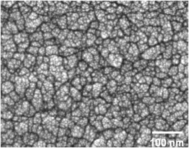
Figure 1 shows a high resolution SEM image of a typical ultra-hard carbon coating grown on CoCrMo using the oxygen feedgas mixture in this study. The morphology shows discrete equiaxed particles of about 5–10 nm in size, with a weak tendency for agglomeration into larger 25–50 nm structures. The larger structures are separated by boundaries (shown as dark contrast) with a width of between 5 and 10 nm. The RMS surface roughness of five coatings prepared under identical conditions was 15 ± 3 nm, as measured by the AFM scans. This is in contrast to microcrystalline diamond coatings that have RMS values typically an order of magnitude higher.
Fig. 1.
SEM image of adhered ultra-hard carbon film with nano-structured morphology grown on CoCrMo alloy
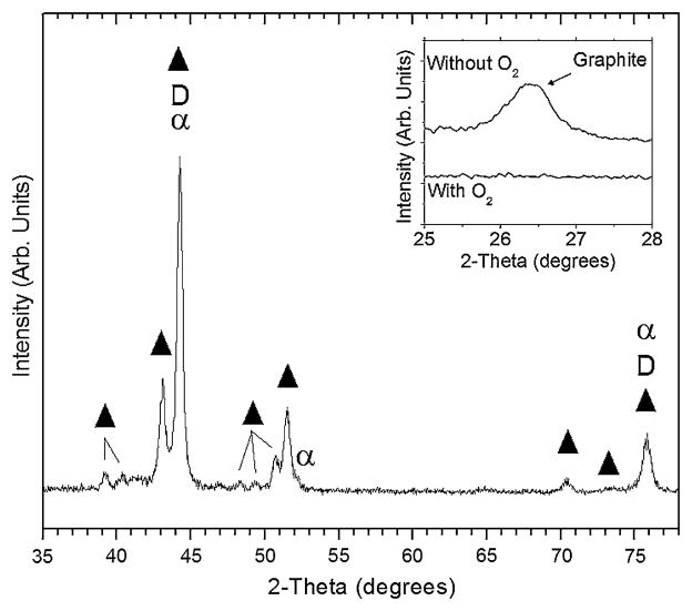
The crystalline structure of the coating/substrate as measured by glancing-angle XRD is shown in Fig. 2 for a 1 μm-thick adhered coating grown using oxygen. Cobalt is known to undergo a phase transformation from hexagonal (ε-Co, stable below 417°C) to face-centered cubic (α-Co, stable from 417 to 1495°C), although both phases may coexist. As a result of the close match in lattice parameter for α-Co and diamond, reflections from these phases overlap and hinder identification of the crystalline cubic diamond phase. However, the remaining primary peaks were indexed to chromium carbide with several stoichiometries including Cr7C3, Cr2C, Cr3C2, and Cr23C6. No crystalline oxide phase was detected. The inset of Fig. 2 shows XRD spectra for films grown with and without oxygen in the 2θ range for observation of the graphite (002) reflection at 2θ = 26.5°. When oxygen is used, no crystalline graphite is detected, whereas it is present when no oxygen is added to the feedgas mixture.
Fig. 2.
Glancing angle XRD pattern of ultra-hard carbon film on CoCrMo showing peaks indexed to chromium carbide (filled triangle), diamond (D), and face-centered cubic cobalt (α). The inset shows XRD patterns for films grown with and without oxygen in the 2-theta range of the graphite (002) reflection. No graphite is detected when oxygen is used
3.2 Surface structure/composition before film coalescence
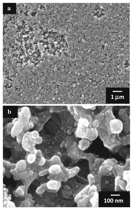
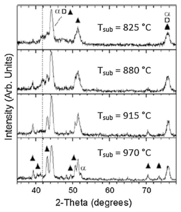
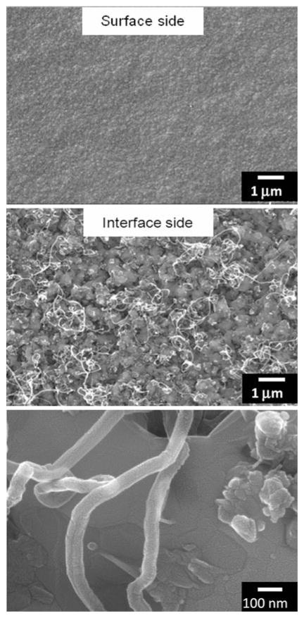
In order to study the influence of oxygen during the nucleation and initial growth phase of CVD carbon films on CoCrMo alloy, deposition was terminated before a continuous carbon layer could form for experiments performed with and without oxygen, and for a range of substrate temperatures. The stopping point was monitored using in situ optical pyrometry by noting the first maximum in the observed optical interference pattern [28]. It was verified from SEM, as shown in Fig. 3, that this stopping point precludes the formation of a continuous carbon film, leaving regions of incomplete surface coverage. These regions show a nodular morphology with nanoscale dimension and high porosity. Glancing-angle XRD was performed on the early-terminated films grown using oxygen for a range of substrate temperatures. As shown in Fig. 4, an evolution of the crystalline structure occurs with increasing temperature observed as an increase in chromium carbide peak intensity and sharpness (i.e. the peaks at 2θ = 39.2, 40.3, 43.1, 49.4, 50.7, 51.6, 70.3, and 73.4°). These peaks correspond to chromium carbide with stoichiometry including Cr3C2, Cr2C, Cr7C3, and Cr23C6. Films grown at lower substrate temperatures (~775°C) tended to delaminate upon cooling to room temperature, while films remained adhered when grown at higher temperature (~970°C). High resolution SEM of the delaminated films shown in Fig. 5 reveals what appear to be carbon nanotubes of about 80 nm diameter on the interface side of the film.
Fig. 3.
SEM images taken just after initial nucleation and growth of ultra-hard carbon film on CoCrMo showing regions of incomplete film coverage at a low and b high magnification
Fig. 4.
Glancing angle XRD patterns after nucleation of ultra-hard carbon film on CoCrMo at different substrate temperature. At higher temperature, intensity of chromium carbide peaks (filled triangle) is increased and cobalt is primarily in FCC (α) phase. Cubic diamond (D) peaks overlap with the other phases. The dashed line indicates the peak indexed to hexagonal cobalt and cobalt carbides that diminish with increasing temperature
Fig. 5.
SEM images showing surface (top) and interface (middle and bottom) morphology from a delaminated ultra-hard carbon film grown on CoCrMo with oxygen at a low substrate temperature (825°C). Carbon nanotubes are observed to develop at the interface
To further elucidate the role of oxygen during initial stages of nucleation/growth, XPS was performed on early-terminated films that were grown with or without oxygen. Figure 6 shows the survey spectra for these films nucleated at a substrate temperature of 915°C. The most striking observation from these spectra is the absence of surface cobalt and molybdenum when oxygen is used in the feedgas. However, surface chromium is present and, as expected, a more intense oxygen peak is detected when oxygen feedgas is used. Table 1 shows the atomic percent ratios for Co/Cr, Co/C, O/Cr, and O/Co on the early-terminated films grown with and without oxygen. The Co/Cr and Co/C ratios drop two orders of magnitude when oxygen is used and as expected the O/Cr and O/Co increase dramatically. Weak peaks for silicon were detected when oxygen was not used, likely from the known alloy impurities.
Fig. 6.
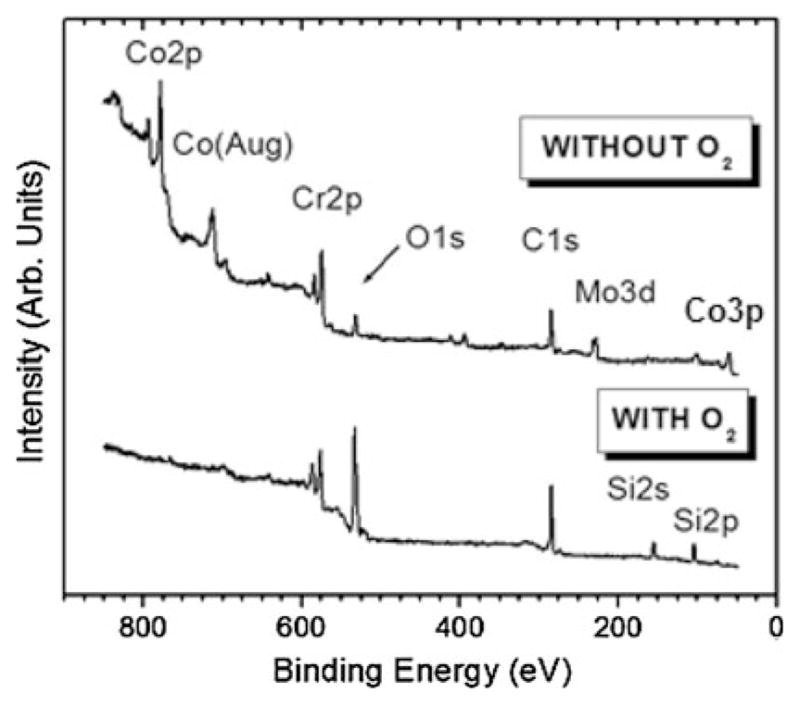
XPS survey spectra after nucleation of ultra-hard carbon films grown on CoCrMo with and without oxygen at Tsub = 915°C. When oxygen is used, no cobalt or molybdenum is detected on the surface, although chromium is still present
Table 1.
XPS atomic percent ratios for nanostructured diamond films grown on CoCrMo, with and without use of oxygen feedgas
| Atomic percent ratio | Without O2 | With O2 |
|---|---|---|
| Co/Cr | 1.6 | 0.027 |
| Co/C | 0.18 | 0.001 |
| O/Cr | 2.0 | 6.4 |
| O/Co | 1.3 | 236 |
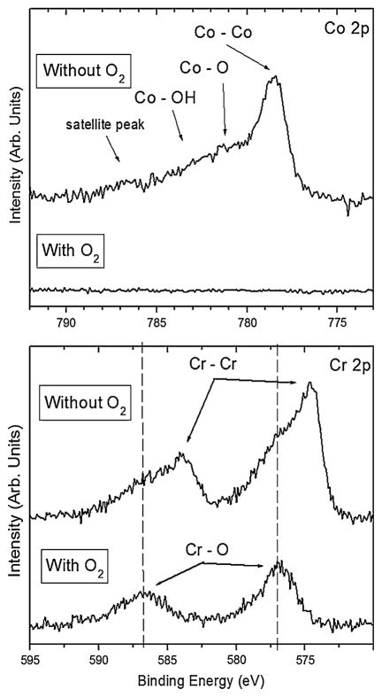
High resolution spectra for Co 2p and Cr 2p, shown in Fig. 7, were taken to determine the nature of bonding with oxygen for these metals in the early-terminated films. While no cobalt was detected when oxygen was used, without the use of oxygen Co 2p spectra show a primary component of elemental cobalt with some bonding as cobalt oxide and cobalt hydroxide. The Cr 2p spectra also show a primarily elemental chromium component when oxygen is not used, along with chromium oxide. However, when oxygen is used, the chromium forms an oxide with essentially no elemental chromium remaining.
Fig. 7.
High resolution XPS spectra for Co 2p and Cr 2p after nucleation of ultra-hard carbon films grown on CoCrMo with and without oxygen at Tsub = 915°C. When oxygen is not used, chromium is detected primarily in elemental form, while it is primarily bonded with oxygen when oxygen is used in the feedgas
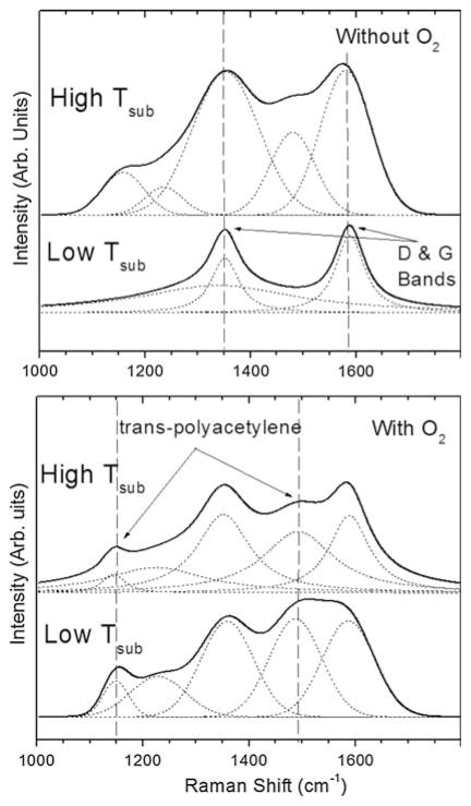
Raman spectra for the early-terminated films grown with or without oxygen at low and high substrate temperature are shown in Fig. 8. It should be noted that in visible Raman spectra the scattering cross section of the sp2 phase is much higher (50–250 times for 514 nm excitation) than that of the sp3 phase [32]. All films show characteristic D and G bands indicative of sp2-bonded carbon. Transpolyacetylene, also often observed in nanostructured diamond films [33], is observed.
Fig. 8.
Raman spectra after nucleation of ultra-hard carbon films grown on CoCrMo with and without oxygen, and for low and high substrate temperature (825 and 970°C, respectively). Without oxygen, graphite carbon is prevalent. With oxygen, polyacetylene (C2H2)n component is reduced relative to D and G bands as temperature is increased
3.3 Structure and mechanical properties of thick adhered coatings
Figure 9 shows Raman spectra for continuous films grown to a thickness of 1 μm for low and high temperature deposition (with oxygen). Although the lower temperature film clearly shows a higher sp3 content as observed by the sharper, more resolved diamond peak at 1332 cm−1, it also shows a relatively high polyacetylene component. The low temperature films delaminated while the high temperature films more consistently remained adhered. The Raman spectra of the high temperature films is similar to that observed for nanostructured diamond [33].
Fig. 9.
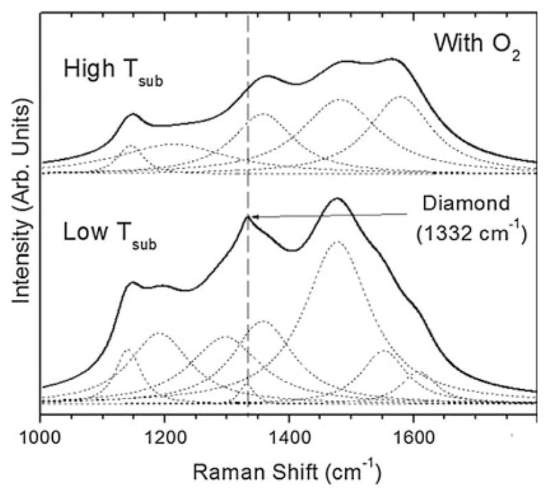
Raman spectra after 1 μm-thick film growth of ultra-hard carbon films grown on CoCrMo with and without oxygen, and for low and high substrate temperature (825 and 970°C, respectively). Although the low temperature film shows higher sp3 carbon content, it delaminates. However, the high temperature film remains adhered
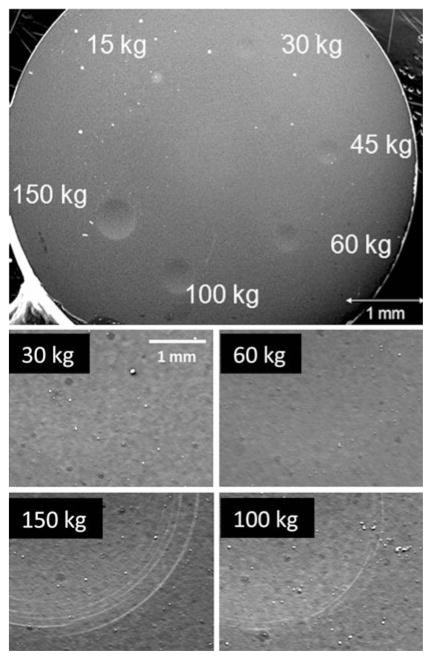
Rockwell indentation was performed on the hard carbon-coated CoCrMo substrates on which films remained adhered, i.e. those grown at temperature between 915 and 970°C. This test provides a qualitative measure of film adhesion by placing the film and the underlying substrate under substantial strain. Figure 10 shows a low magnification optical micrograph of a typical hard carbon-coated CoCrMo substrate after making six indents with 15, 30, 45, 60, 100, and 150 kg loads, respectively. Five hard carbon-coated CoCr substrates were indented, each with these six loads. No delamination was observed for any of the indents made. The residual depth of indentation craters measured from profilometry averaged 25 μm for the 150 kg load. SEM images of the indents made using 30, 60, 100, and 150 kg loads are also shown in Fig. 10. Circumferential microcracks were observed from SEM images just within and near the edges of indent craters, as shown in Fig. 10. These cracks were only observed for the 100 and 150 kg indent loads. However, the film remained intact for all indentation loads and showed no sign of delamination.
Fig. 10.
Optical micrograph showing ultra-hard carbon-coated CoC-rMo substrate after Rockwell indentation using 15, 30, 45, 60, 100, and 150 kg loads. No film delamination was observed after indentation at these loads. The film undergoes plastic deformation without hard elastic-to-brittle failure through the formation of circumferential microcracks around the edges of indent craters, as observed for 100 and 150 kg indents
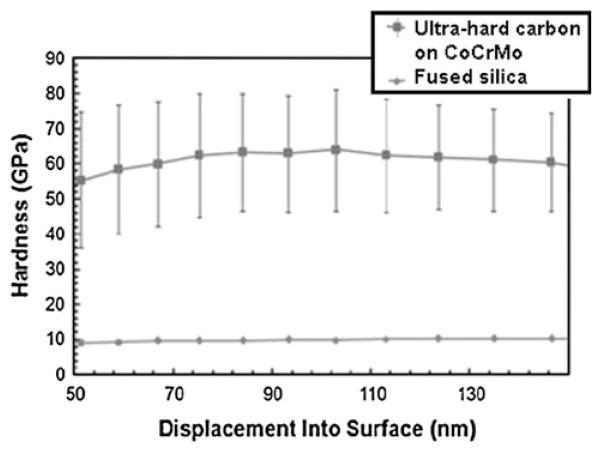
The nanoindentation hardness vs. indentation depth (from 50 to 150 nm) for an adhered hard carbon coating on CoCrMo is shown in Fig. 11. Four random areas of the sample were measured with five indents made per area; each indent separated by 50 μm. For reference, fused silica (with known hardness of 9.5 GPa) was tested along with the CVD hard carbon films. The measured hardness for the film ranged from 45 to 80 GPa. The average hardness measured throughout the depth of indentation is 60 ± 15 GPa.
Fig. 11.
Nanoindentation hardness on surface of 1 μm-thick adhered ultra-hard carbon film (filled square) grown on CoCrMo at high substrate temperature (970°C). The hardness measured on fused silica (filled circle) is also provided for comparison. Each data point represents average of eight indents measured at different locations of the sample
4 Discussion
The films grown in this study are smooth with an RMS roughness of 15 nm, as a result of very small particle size on the order of 5–10 nm. The transition from faceted microcrystalline diamond to smooth nanostructured carbon may occur via several different CVD processing pathways. We have previously shown that for diamond films grown on titanium alloys this transition from micro to nano can occur with addition of nitrogen into a H2/CH4 feedgas mixture, even for high methane fractions of 15% (by volume) [34]. Faceted crystalline diamond films were shown to be grown using such high methane fraction under conditions of high operating pressure (125 Torr) where copious amounts of atomic hydrogen are generated. For growth on CoCrMo alloy, we found the use of nitrogen to produce interfacial chromium nitride phases that did not provide an effective diffusion barrier to cobalt, and therefore coating adhesion was poor. However, when substituting oxygen for nitrogen and using a lower operating pressure (40 Torr), we were able to achieve smooth and adhered ultra-hard carbon coatings on this alloy.
The role of oxygen in CVD diamond growth has been studied and it is well established that oxygen preferentially etches non-diamond carbon (including graphite), increases the sp3 carbon content, and extends the range of substrate temperature for high quality diamond growth [23–27]. However, conventional CVD diamond growth on surfaces rich in iron, nickel, or cobalt leads to copious amounts of graphitic soot as a result of the strong catalytic effect of carbon with these transition metals. Therefore, oxygen serving only as an etchant during CVD diamond growth is, by itself, not expected to be sufficient to overcome the dominant driving force for graphite formation on these metals. While diamond may grow over an interfacial graphitic layer, the adhesion of the diamond to the substrate is very poor.
XRD results show that chromium carbide with several stoichiometries (including Cr3C2, Cr2C, Cr7C3, and Cr23C6) is the predominant interfacial crystalline phase that forms in this system. Early-terminated films (before coalescence occurs) show regions of nodular morphology with nanoscale dimension and high porosity. Similar morphology for carburized CoCrMo has been reported as resembling “brain coral” and was shown to contain several stoichiometric phases of chromium carbide [35, 36]. From a Gibbs free energy (ΔG) standpoint, the driving force for formation of chromium carbide is higher (ΔG is more negative) than cobalt carbide by as much as 80 kJ/mol at a temperature of 900°C. The chromium carbide content and crystallinity increase with temperature as observed by an increase in XRD peak intensity and sharpness. The XRD peak at 41.8° present at 825 and 880°C is not observed at the higher temperatures. The origin of this peak is not certain, but it can be indexed to cobalt carbide (both Co2C and Co3C) and/or hexagonal cobalt. If it is due to cobalt carbide, it suggests that cobalt is more able to react with carbon at low temperature than at high temperature in this system. In either case, energy dispersive X-ray microanalysis (not shown) revealed the presence of cobalt in delaminated films grown at lower temperature. Considering that film delamination was observed to occur more at low temperature (880°C and below) even when oxygen is used, suggests that the presence of cobalt migrating into the growing film may be responsible for the poor adhesion.
The observation of carbon nanotubes on the interface side of the delaminated films lends further support to the presence of cobalt which is well known to act as a catalyst for formation of these structures [37, 38]. Film adhesion is expected to be poor when nanotubes or other graphite-containing structures exist at the interface. One might suggest that an interfacial carbide layer may itself be sufficient to act as a diffusion barrier to elemental cobalt. However, substantial graphitic soot is formed and adhesion is poor when oxygen is not used, even at the higher temperatures. Therefore, oxygen plays an important role in achieving soot-free, adhered carbon films on CoCrMo, particularly for the substrate temperature range of 915 to 970°C. The inset in Fig. 2 shows the dramatic effect of oxygen in preventing graphite. Oxygen is believed to readily form an interfacial chromium oxide layer that acts as a diffusion barrier to cobalt, thus preventing its catalytic effect in forming graphite. XPS results (Fig. 6) confirm that oxygen creates a barrier to cobalt and molybdenum migration to the surface, while chromium is able to bond to oxygen on the surface. In fact, as seen by the high-resolution XPS spectra (Fig. 7), chromium oxide is more prevalent when oxygen is used, indicating that it acts at least in major part as a barrier to cobalt. The Co/Cr and Co/C ratios (Table 1) drop two orders of magnitude when oxygen is used and as expected the O/Cr and O/Co increase dramatically. Chromium carbide may also contribute to the diffusion barrier, but to a lesser extent since graphite still forms when oxygen is not used.
These results point to the importance of suppressing cobalt surface migration during nucleation/growth of hard carbon films through the use of oxygen in the feedgas. The kinetics of chromium oxide formation is also important so that this non-catalyst containing diffusion barrier can quickly form and mask the deleterious interaction of cobalt with carbon during diamond nucleation and growth. While kinetics is not investigated here, it is useful to consider the standard Gibbs free energy of formation (ΔG) for chromium oxides compared with cobalt oxides, thereby providing a measure of the driving force for the reaction to occur. At a temperature of 900°C, ΔG for cobalt to form CoO is −302 kJ/mol and ΔG is −19 kJ/mol to form Co3O4. By comparison, for chromium to form Cr2O3 at the same temperature ΔG is −544 kJ/mol. The more negative value of ΔG indicates a larger driving force for the reaction to occur, and so it is expected that chromium oxide would form preferentially over cobalt oxide. This is beneficial for growth of hard carbon films in potentially acting as a barrier to up-diffusion of cobalt from the substrate. Chromium oxide has been shown to be an effective diffusion barrier for a number of material systems [39–42].
The Raman spectra for the early-terminated films grown with or without oxygen at low and high substrate temperature (Fig. 8) reveal that the deposited carbon films are not phase pure diamond, but consist of nanocrystalline diamond along with sp2- and sp3-amorphous carbon components. The G peak (1580 cm−1) is due to the bond stretching of all pairs of sp2 atoms in both rings and chains. The D peak (1350 cm−1) is due to the breathing modes of sp2 atoms in rings. At low temperature without oxygen, the main Raman component consists of relatively sharp D and G bands and indicates a primarily ordered graphitic structure. This is consistent with observation of a black sooty appearance on the surface. At high temperature without oxygen, broadened D and G bands are accompanied by bands centered at 1150 cm−1 and 1480 cm−1 assigned to transpolyacetylene (C2H2) structure [43]. Broadening of the G band indicates more disorder and the film includes amorphous carbon with some sp3 content and decreasing sp2 grain size. With oxygen added to the feedgas, the polyacetylene component increases, particularly at low temperature, and the films show Raman spectra more representative of nanocrystalline diamond [43]. Also with oxygen, we see a general decrease in the ratio of D/G band intensity I(D)/I(G) that suggests a higher sp3 content. However, the sp2 content is slightly higher at the higher temperature. These results are consistent with previous studies describing improved quality of diamond films grown using oxygen [23–26].
Thick films (1 μm thick) grown using oxygen typically delaminated after CVD processing at low substrate temperature, while more consistently remained adhered after processing at the high temperatures (915–970°C). The poor adhesion of the low temperature films may be due to several combined factors, including (1) higher cobalt content leading to observed carbon nanotube and graphite formation at the interface, (2) reduced chromium carbide content that would otherwise act to reduce interfacial stress, (3) higher hydrogen content from polyacetylene formation leading to increased film stress, and (4) higher sp3 content with subsequent reduction in film fracture toughness. XPS results clearly show that oxygen is important for creating interfacial chromium oxides that minimize interaction of cobalt with the growing carbon film, even at elevated temperature. The chromium oxide effectively acts as a diffusion barrier to cobalt, thus reducing nucleation of graphite and/or carbon nanotubes that hinder film adhesion.
Rockwell indentation (Fig. 10) shows that the adhered coating can withstand very large plastic deformation without delamination as it expands with the underlying metal. Strain energy is accommodated in part through stable circumferential microcracks around the indent edge. The degree of film cracking with increasing indentation load can be an indicator of film toughness and interfacial adhesion. Clearly, the ultra-hard carbon films on CoCrMo can undergo significant plastic deformation without hard elastic-to-brittle fracture occurring [44]. The coating may be described as a nanocomposite containing nanoscale diamond grains embedded in a more ductile amorphous carbon matrix. The amount of strain accommodation in such coatings is particularly high for a superhard material and is a feature observed in other hard/tough nanocomposite systems such as those involving titanium carbide particles in an amorphous carbon matrix [45]. Small cracks that may develop are not catastrophic, but terminate within the surrounding amorphous matrix, which acts to relax incoherence stress and distribute the localized load over larger volumes [46]. Therefore, residual stresses may be more effectively relaxed when compared with a highly crystalline, more brittle and homogeneous ceramic.
Nanoindentation hardness data indicate that the coatings are quite hard (60 ± 15 GPa), well exceeding that of diamond-like carbon (DLC) films. The spread in hardness values indicates sample inhomogeneity on the scale of the indenter (having tip radius of 50 nm). The ultra-hard carbon coating is believed to contain nanoscale diamond crystals embedded in an amorphous carbon matrix. On this indentation scale, the indenter may probe regions that are harder (diamond crystals) or softer (amorphous carbon) leading to the spread in measured hardness. Future work will include tribological and cyclic fatigue evaluation of the coatings.
5 Conclusions
The interaction of cobalt with carbon during conventional CVD diamond and diamond-like carbon growth has historically precluded the use of CoCrMo orthopedic devices as potential candidates for these coatings due to poor adhesion. In this study, the use of oxygen added to a H2/CH4 feedgas mixture is shown to mask the catalytic effect of cobalt with carbon through formation of an interfacial chromium oxide layer. The ultra-hard carbon coatings grown with oxygen on CoCrMo at substrate temperature in the range of 915–970°C show excellent adhesion, while those grown at lower temperatures or without oxygen delaminate. Despite the expected increase of thermally-induced stress at the elevated temperature, improved adhesion of these coatings is attributed to higher interfacial chromium carbide content and reduced cobalt migration into the growing film. In contrast, the films grown at lower temperature show the presence of carbon nanotubes at the interface side of delaminated films, indicative of cobalt interaction with carbon. Overall, these results provide hope for successful ultra-hard carbon coating of CoCrMo orthopedic implant materials for improved joint performance and lifetime. Artificial joints involving articulation with ultra-hard carbon may be a viable option leading to fewer and less invasive surgeries while maintaining high performance of the joint.
Acknowledgments
We acknowledge support by Award Number R01AR056665 from the National Institute of Arthritis and Musculoskeletal and Skin Diseases. The content is solely the responsibility of the authors and does not necessarily represent the official views of the National Institute of Arthritis and Musculoskeletal and Skin Diseases or the National Institutes of Health. The authors thank Smith & Nephew, Inc. for providing the CoCrMo disks used in this study.
Contributor Information
Shane A. Catledge, Email: catledge@uab.edu, Department of Physics, University of Alabama at Birmingham (UAB), 310 Campbell Hall, Birmingham, AL 35294-1170, USA
Rishi Vaid, Department of Physics, University of Alabama at Birmingham (UAB), 310 Campbell Hall, Birmingham, AL 35294-1170, USA.
Patrick Diggins, IV, Department of Physics, University of Alabama at Birmingham (UAB), 310 Campbell Hall, Birmingham, AL 35294-1170, USA.
Jeffrey J. Weimer, Chemistry/Chemical & Materials Engineering, University of Alabama at Huntsville (UAH), MSB 125, Huntsville, AL 35899, USA
M. Koopman, Department of Physics, University of Alabama at Birmingham (UAB), 310 Campbell Hall, Birmingham, AL 35294-1170, USA
Yogesh K. Vohra, Department of Physics, University of Alabama at Birmingham (UAB), 310 Campbell Hall, Birmingham, AL 35294-1170, USA
References
- 1.Black J. Biological performance of materials: fundamentals of bio-compatibility. New York: Marcel Dekker; 1992. [Google Scholar]
- 2.American Academy of Orthopaedic Surgeons. 2006. [Google Scholar]
- 3.Amstutz HC, Campbell P, Kossovsky N, Clarke IC. Mechanism and clinical significance of wear debris-induced osteolysis. Clin Orthop Relat Res. 1992;(276):7–18. [PubMed] [Google Scholar]
- 4.Goldring SR, Schiller AL, Roelke M, Rourke CM, O’Neil DA, Harris WH. The synovial-like membrane at the bone-cement interface in loose total hip replacements and its proposed role in bone lysis. J Bone Joint Surg Am. 1983;65(5):575–84. [PubMed] [Google Scholar]
- 5.Amstutz HC, Grigoris P. Metal on metal bearings in hip arthroplasty. Clin Orthop Relat Res. 1996;329(Suppl):S11–34. doi: 10.1097/00003086-199608001-00003. [DOI] [PubMed] [Google Scholar]
- 6.McKellop H, Park SH, Chiesa R, Doorn P, Lu B, Normand P, Grigoris P, Amstutz H. In vivo wear of three types of metal on metal hip prostheses during two decades of use. Clin Orthop Relat Res. 1996;329(Suppl):S128–40. doi: 10.1097/00003086-199608001-00013. [DOI] [PubMed] [Google Scholar]
- 7.Medley JB, Chan FW, Krygier JJ, Bobyn JD. Comparison of alloys and designs in a hip simulator study of metal on metal implants. Clin Orthop Relat Res. 1996;329(Suppl):S148–59. doi: 10.1097/00003086-199608001-00015. [DOI] [PubMed] [Google Scholar]
- 8.Wagner M, Wagner H. Medium-term results of a modern metal-on-metal system in total hip replacement. Clin Orthop Relat Res. 2000;(379):123–33. doi: 10.1097/00003086-200010000-00015. [DOI] [PubMed] [Google Scholar]
- 9.Hallab N, Merritt K, Jacobs JJ. Metal sensitivity in patients with orthopaedic implants. J Bone Joint Surg Am. 2001;83A(3):428–36. doi: 10.2106/00004623-200103000-00017. [DOI] [PubMed] [Google Scholar]
- 10.Moran CG, Tourret LJ. Recent advances: orthopaedics. BMJ. 2001;322(7291):902–5. doi: 10.1136/bmj.322.7291.902. [DOI] [PMC free article] [PubMed] [Google Scholar]
- 11.Kobayashi S, Ohgoe Y, Ozeki K, Hirakuri K, Aoki H. Dissolution effect and cytotoxicity of diamond-like carbon coatings on orthodontic archwires. J Mater Sci Mater Med. 2007;18(12):2263–8. doi: 10.1007/s10856-007-3118-2. [DOI] [PubMed] [Google Scholar]
- 12.Ohgoe Y, Kobayashi S, Ozeki K, Aoki H, Nakamori H, Hirakuri KK, Miyashita O. Reduction effect of nickel ion release on a diamond-like carbon film coated onto an orthodontic archwire. Thin solid Films. 2006;497(1–2):218–22. [Google Scholar]
- 13.Lettington A, Steeds JW. Thin film diamond. London: Chapman and Hall; 1994. [Google Scholar]
- 14.Davis RF. Diamond films and coatings. Park Ridge: Noyes Publications; 1993. [Google Scholar]
- 15.Chen X, Narayan J. Effect of the chemical nature of transition-metal substrates on chemical-vapor deposition of diamond. J Appl Phys. 1993;74(16):4168–73. [Google Scholar]
- 16.Godbole VP, Narayan R, Xu Z, Narayan J, Sankar J. Diamond films and composites on cobalt–chromium alloys. Mater Sci Eng B. 1999;58:251–7. [Google Scholar]
- 17.Wei Q, Yu Z, Ma L, Yin D. Enhanced nucleation and smoothness of nanocrystalline diamond films via W–C gradient interlayer. Int J Mod Phys B. 2009;23(6–7):1676–82. [Google Scholar]
- 18.Polini R, Mantini FP, Braic M, Amar M, Ahmed W, Taylor H, Jackson MJ. Effects of Ti- and Zr-based interlayer coatings on hot-filament chemical vapor deposition of diamond on high-speed steel. J Mater Eng Perform. 2007;15(2):201–7. [Google Scholar]
- 19.Zuo D, Li XF, Wang M, Li L, Lu WZ. Adhesion improvement of CVD diamond film by introducing an electro-deposited inter-layer. J Mat Proc Technol. 2003;138:455. [Google Scholar]
- 20.Narayan J, Godbole VP, White CW. Laser method for synthesis and processing of continuous diamond films on nondiamond substrates. Science. 1991;252(5004):416–8. doi: 10.1126/science.252.5004.416. [DOI] [PubMed] [Google Scholar]
- 21.Lee S-T, Chen S, Agostinelli J, Braunstein G, Huang LJ, Lau WM. Laser processing of carbon-implanted Cu, Ni, and Co crystals—an attempt to grow diamond films. Appl Phys Lett. 1992;60:2213–5. [Google Scholar]
- 22.Neto MA, Pereira E. Influence of oxygen and nitrogen addition during growth of CVD diamond on pure cobalt substrates. Diam Relat Mater. 2006;15:465–71. [Google Scholar]
- 23.Liou Y, Inspektor A, Weimer R, Knight D, Messier R. The effect of oxygen in diamond deposition by microwave plasma enhancement chemical vapor deposition. J Mater Res. 1990;5:2305–12. [Google Scholar]
- 24.Shah SI, Waite MM. Effect of oxygen on the nucleation and growth of diamond thin films. Appl Phys Lett. 1992;61:3113. [Google Scholar]
- 25.Kawato T, Kondo K. Effects of Oxygen on CVD diamond synthesis. Jpn J Appl Phys. 1987;26:1429–32. [Google Scholar]
- 26.Tang J, Neves AJ, Fernandes AJS. Study the effect of O2 addition on hydrogen incorporation in CVD diamond. Diam Relat Mater. 2004;13(1):203–8. [Google Scholar]
- 27.Dementjev AP, Petukhov MN. The role of oxygen atoms in sp2–sp3 conversion on the growing surface of carbon film. In: Gielisse PJ, Ivanov-Omskii VI, Popovici G, Prelas M, editors. Diamond and diamond-like film applications. Lancaster, PA: Technomic Publishing Company, Inc; 1998. [Google Scholar]
- 28.Catledge SA, Comer W, Vohra YK. In situ diagnostics of film thickness and surface roughness of diamond films on a Ti–6Al–4V alloy by optical pyrometry. Appl Phys Lett. 1998;73:181–3. [Google Scholar]
- 29.McHargue J. Mechanical properties of diamond and diamond-like films. In: Tzeng Y, Yoshikawa M, Murakawa M, Feldman A, editors. Applications of diamond films and related materials. Amsterdam: Elsevier; 1991. p. 113. [Google Scholar]
- 30.Fabes BD, Oliver WC, McKee RA, Walker FJ. The determination of film hardness from the composite response of film and substrate to nanometer scale indentations. J Mater Res. 1992;7:3056. [Google Scholar]
- 31.Oliver WC, Pharr GM. An improved technique for determining hardness and elastic modulus using load and displacement sensing indentation experiments. J Mater Res. 1992;7:1564. [Google Scholar]
- 32.Salis SR, Gardiner DJ, Bowden M, Savage J, Rodway D. Monitoring the quality of diamond films using Raman spectra excited at 514.5 nm and 633 nm. Diam Relat Mater. 1996;5:589. [Google Scholar]
- 33.Ferrari AC, Robertson J. Raman spectroscopy of amorphous, nanostructured, diamond-like carbon, and nanodiamond. Philos Trans A Math Phys Eng Sci. 2004;362(1824):2477–512. doi: 10.1098/rsta.2004.1452. [DOI] [PubMed] [Google Scholar]
- 34.Catledge SA, Vohra YK. Effect of nitrogen addition on the microstructure and mechanical properties of diamond films grown using high-methane concentrations. J Appl Phys. 1999;86:698. [Google Scholar]
- 35.Vandamme NS, Topoleski LD. Control of surface morphology of carbide coating on Co–Cr–Mo implant alloy. J Mater Sci Mater Med. 2005;16(7):647–54. doi: 10.1007/s10856-005-2536-2. [DOI] [PubMed] [Google Scholar]
- 36.Vandamme NS, Que L, Topoleski LDT. Carbide surface coating of Co–Cr–Mo implant alloys by a microwave plasma-assisted reaction. J Mater Sci. 1999;34:3525–31. [Google Scholar]
- 37.Wu WT, Chen KH, Hsu CM. Growth of carbon nanotubes on cobalt catalyst film using electron cyclotron resonance chemical vapour deposition without thermal heating. Nanotechnology. 2006;17:4542–7. doi: 10.1088/0957-4484/17/18/003. [DOI] [PubMed] [Google Scholar]
- 38.Bethune DS, Klang CH, Vries MSd, Gorman G, Savoy R, Vaz-quez J, Beyers R. Cobalt-catalysed growth of carbon nanotubes with single-atomic-layer walls. Nature. 1993;363:605–7. [Google Scholar]
- 39.Samingprai S, Tantayanon S, Ma YH. Chromium oxide inter-metallic diffusion barrier for palladium membrane supported on porous stainless steel. J Memb Sci. 2010;347(1–2):8–16. [Google Scholar]
- 40.Ezhovskii YK, Egorov AL. Characteristics of the interfaces and the properties of chromium oxide nanolayers on gallium arsenide. Phys Solid State. 2007;49(9):1638–42. [Google Scholar]
- 41.Hegedus C, Daroczi L, Kokenyesi V, Beke DL. Comparative microstructural study of the diffusion zone between NiCr alloy and different dental ceramics. J Dent Res. 2002;81(5):334–7. doi: 10.1177/154405910208100509. [DOI] [PubMed] [Google Scholar]
- 42.Yang HDZ, Libera M, Jacobson DC, Wang YC, Davis RF. Structural and chemical characteristics and oxidation behaviour of chromium-implanted single crystal silicon carbide. J Mater Sci. 1995;30(10):2668–74. [Google Scholar]
- 43.Ferrari AC, Robertson J. Raman spectroscopy of amorphous, nanostructured, diamond-like carbon, and nanodiamond. Philos Trans Math Phys Eng Sci. 2004;362:2477–512. doi: 10.1098/rsta.2004.1452. [DOI] [PubMed] [Google Scholar]
- 44.Toprani N, Catledge SA, Vohra YK, Thompson R. Interfacial adhesion and toughness of nanostructured diamond coatings. J Mater Res. 2002;15:1052. [Google Scholar]
- 45.Voevodin AA, Zabinski JS. Load-adaptive crystalline-amorphous nanocomposites. J Mater Sci. 1998;33:319. [Google Scholar]
- 46.Leyland A, Matthews A. On the significance of the H/E ratio in wear control: a nanocomposite coating approach to optimised tribological behavior. Wear. 2000;246:1. [Google Scholar]


