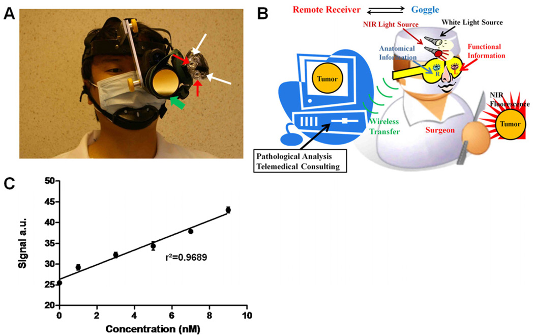
Figure 1.
Prototype intraoperative fluorescence imaging device. (A) Picture of the imaging device. Green arrows: detector; red arrows: NIR light sources; white arrows: white light sources. (B) Overview of the imaging system in a schematic diagram. Surgeon can capture functional information with one eye, while simultaneously obtaining anatomical information with the other eye. Real-time video can be transferred wirelessly to a remote site. (C) Sensitivity test of the device. NIR signal intensity versus indocyanine green concentration is plotted. Dots: mean values; error bars: standard deviation; r2: linear regression coefficient.

