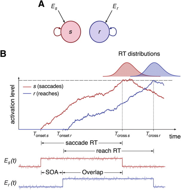
Figure 2.
Dual integrator model. A, Diagram of the integrator model for a dual reaction time task. Each filled circle corresponds to an integrator, each of which receives specific external input Ei (i = s,r stands for saccades and reaches, respectively). Self-directed arrows represent the recurrent inputs within a unit. B, Schematic of the integrate-to-threshold process for the initiation of saccades and reaches. When the go cue signal for the saccade appears at time t = Tonset s, the input to the saccade unit is switched on and the unit starts integrating the input. Similarly, the reach unit starts integrating after the onset of the go cue signal for reaches, at time t = Tonset r = Tonset s + SOA. According to the model, the initiation of saccades and reaches is given by the times of threshold crossing Tcross s and Tcross r, respectively. The bottom panel shows the time course of the external inputs Es(t) and Er(t), which consist of a step current perturbed by additive noise. Each current is switched off when the associated integrator variable hits threshold.

