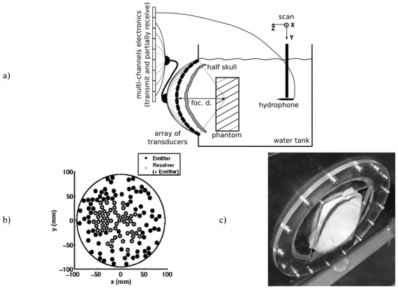
Figure 1.

a) Experimental setup. The drawn configuration corresponds to the part of the experiment where bubbles were induced in the phantom. When the hydrophone is used, the phantom was removed and the device was moved in the vicinity of the geometrical focus of the array. b) Front view of the spherical array. The colored circles represent the projection of the transducers’ positions. Black filled circles: transducers only connected to an emitting channel. Gray filled circles: transducers connected to a both emitting and receiving channel. The transducers that both transmit and receive are clustered predominately in the central portion of the array since a quite good spacial sampling of the receive array wanted to be kept, so as to reduce grating lobes. c) Picture of the half-skull mounted on the stereotactic positioning system and positionned in front of the ultrasound array.
