
Figure 7. Interaction potential of BST-2 with Vpu and Vpu-A18H.
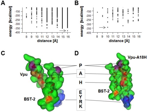
Interaction energies of the BST-2/Vpu (A) and BST-2/Vpu-A18H (B) TMD assemblies in relation to their interhelical distance as determined by a packing protocol using MOE script language. Dots represent individual structures. Arrows indicate the lowest energy structures. Representation of the lowest energy structures of BST-2/Vpu (C) and BST-2/Vpu-A18H (D) in the ‘Gaussian contact’ mode of the MOE suite. The backbone is indicated in a ribbon representation; hydrophobic residues are shown in green, prolines in violet, alanines in orange, BST-2-G25 in yellow-orange, His-18 in red, and a hydrophilic motif of Vpu, EYRK, in blue. The boxed “A” indicates four alanines in the Vpu (A7, A10, A14, and A18) that are on one face of the TMD helix.