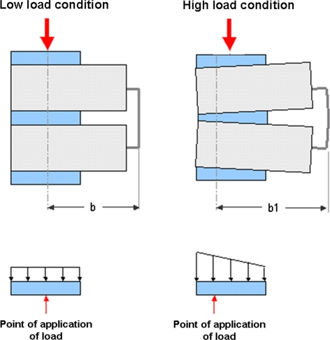
Fig. 4.
Schematic representation of the response of the VMU to low and high load regimen. In particular, the picture highlights how the point of application of the load (“b”) moves forward at high load condition (“b1”, with “b1” > “b”), because of the bending of the hardware, making the system more efficient

