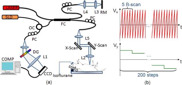
Fig. 1.

(a) Schematic of the UHS-OMAG system: SLD – super luminescent diode, OC – optical circulator, FC– 10:90 fiber coupler, PC – polarization controller, RM – reference mirror, Laser- pilot laser for beam guiding, DG – diffraction grating, CCD – line-scan camera, COMP – computer. (b) Scanning voltage pattern for galvo-mirror during UHS-OMAG data acquisition.
