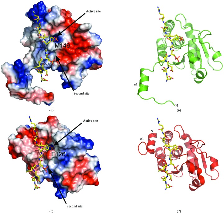
Figure 6.
(a) Surface representation of the crystal structure of DUSP27 with the computed electrostatic surface potential. Positively charged regions are depicted in blue and negatively charged regions in red. The position of the of the DDE(Nle)pTGpYVATR peptide (yellow sticks), a VHR substrate, was modeled based on superposition of DUSP27 with the VHR–peptide complex (PDB code 1j4x). (b) The same view as in (a) illustrated in green ribbon format. (c) Electrostatic surface representation of the crystal structure of the VHR–DDE(Nle)pTGpYVATR peptide complex (PDB code 1j4x). The peptide is illustrated in yellow stick format. (d) The same view as in (c) illustrated in red ribbon format.

