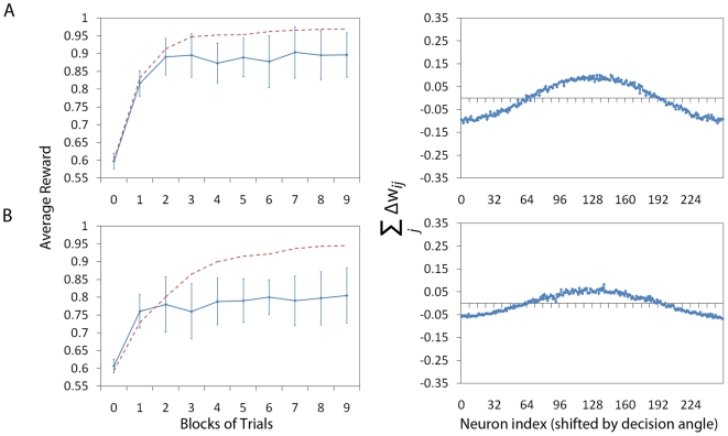
Figure 5. Overlapping receptive fields.
Figure shows the effect of increasing the overlap of the receptive
fields (to  ) of
the Place Cells. Panel A shows a configuration without lateral
connections and panel B shows a configuration with lateral
connections (and corresponds to systems A and B from Figures 3 and
4). The
plots of the average reward (left column, solid line) are calculated
in exactly the same way as in Figure 3 shown over 9 blocks of
512 trials, rather than 5. The red dashed line shows the values from
Figure 3
over 9 blocks for direct comparison. We can observe that the system
without lateral connections is less affected by the increase of the
 parameter than the system with lateral connections. The plots of the
gradient (right column) are produced as in Figures 3 and 4, by plotting the
sum of the potential weight change (calculated in the same way as in
previous figures).

