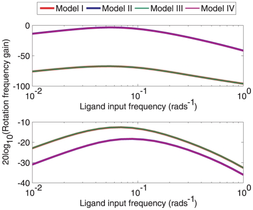
Figure 8. Input-output gains of the two sensing clusters.
Frequency response magnitude plots showing the response of the different models to sinusoidally-varying ligand concentrations modelling noisy ligand input signals. Top: Constant ligand to cytoplasmic cluster and variable ligand to polar cluster ( , where
  ). Bottom: Constant ligand to polar cluster, sinusoidal to cytoplasmic cluster (
 , where
  ).
).

