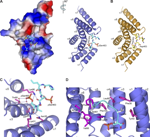
FIGURE 3.
Smad1 C-terminal peptides bind to CHIP-TPR. A, shown is the crystal structure of CHIP-TPR in complex with phosphorylated Smad1 peptide. The two views of the structure are related by a 90° rotation around a vertical axis. The Smad1 peptide is shown as cyan sticks. In the left panel, CHIP-TPR is shown in surface representation and colored according to electrostatic potential (positive, blue; negative, red). The yellow arrows indicate the hydrophobic pockets on CHIP-TPR accommodating Ile-461 and Val-464 of Smad1. In the right panel, CHIP-TPR is colored in slate, and the α-helices are labeled α1 to α7 from the N to C termini. B, shown is a schematic representation of CHIP-TPR (orange) in complex with pseudophosphorylated Smad1(DVD) peptide (yellow). C, hydrogen bond networks at the interface of CHIP-TPR and Smad1 phosphopeptide are shown. The residues on CHIP-TPR are highlighted in magentas sticks. Hydrogen bonds among oxygen (red) and nitrogen (blue) atoms and water molecules (red) are indicated by blue dashed lines. D, van der Waals contacts between CHIP-TPR and Smad1 phosphopeptide are shown. The Smad1 peptide is shown as a cyan ribbon, and the hydrophobic residues are highlighted in gray sticks.

