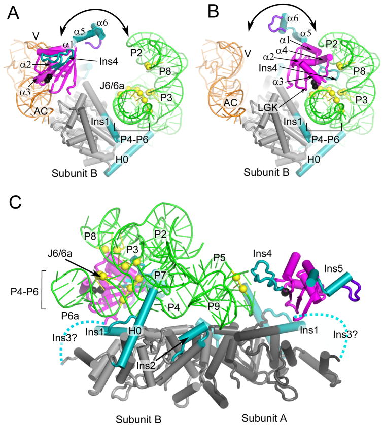
Figure 8.
The An mt TyrRS N- and C-terminal domain function together to clamp the two ends of the group I intron RNA. The models are the same as in Figure 7. (A) Model for subunit B in tRNA-binding mode viewed looking down the P4–P6 helical axis. (B) Model for subunit B in intron-binding mode viewed looking down the P4–P6 stacked helices. The view shows that the position of the C-terminal domain of subunit B satisfies distant restraints based on directed hydroxyl-radical cleavage experiments (see legend Figure 7) between G529 and A530 (black spheres) and Twort ribozyme phosphodiester backbone positions in P6a: 95–97; J6/6a-P6: 112–114; P3: 162, 163; P8: 178, 179 (yellow spheres). (C) Model for group I intron binding viewed perpendicular to P4–P6 domain axis showing C-terminal domains from both subunits. The view shows that the position of C-terminal domain of subunit A satisfies distance restraints between A530 (black sphere) and phosphodiester backbone cleavages at P5a positions 61 and 62 (yellow spheres). Dashed lines represent the Ins3/linker connecting the N- and C-terminal domains. The intron RNA peripheral structures P9.2, P7.1, P7.2 have been removed for clarity.

