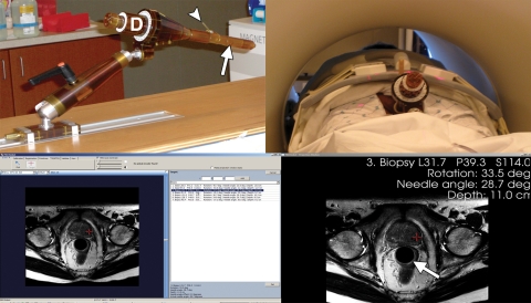
Figure 11.
MR imaging–guided prostate biopsy. Photographs (top) and computer screens (bottom) show use of an MR imaging–compatible biopsy device (72). The device (top left) has an endorectal probe (arrow), a needle guide (arrowhead), and a set of dials (D), which allow the needle to be directed to the target on the basis of input from the targeting software (bottom left). The software provides the necessary angles for probe rotation, needle angulation, and needle depth (bottom right). The dials are adjusted manually by the operator on the basis of software calculations derived from prebiopsy targeting MR images. The patient is placed in the prone position (top right) with endorectal placement of the biopsy probe (arrow at bottom right).

