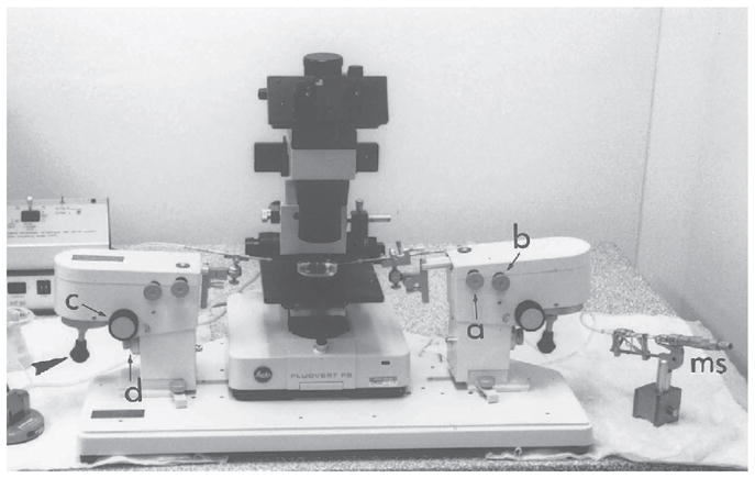
Fig. 6.

The micromanipulation assembly. The manipulators are clamped to the base plate. Each manipulator can hold up to two instrument holders. Movement of the instruments is controlled by screw-knobs (a and b) that allow positioning of the manipulator in the X–Y horizontal plane. There is a third control (c) by which the angle of inclination of the manipulator can be adjusted. Coarse and fine adjustment of the position of the manipulator in the Z-vertical plane is controlled by the fourth knob (d). Fine X–Y movement of the instrument under the microscope is controlled by joysticks (arrowhead). The holding instrument is on the left-hand side of the assembly and the suction and expulsion of fluid are controlled by the micrometer syringe (ms) on the right-hand side. Conversely, the manipulating (labeling or grafting) instruments are on the right-hand side, controlled by the de Fonbrune syringe (fs) on the left-hand side. This setup enables the positioning of the instruments and the control of syringe to be accomplished simultaneously.
