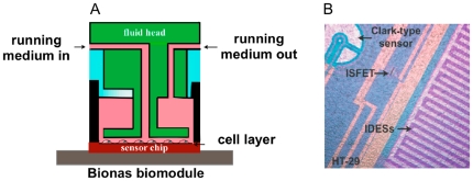
Figure 1. Outline of the cell biosensor chip system.
A, schematic diagram of the flow system for biosensor chip analysis, showing the inlet and outlet for running medium and the small incubation chamber. B, picture of cells (HT29) growing on biosensor chip. Electrode sensors are visible and marked: ISFET: pH sensor; Clark-type sensor: O2 sensor; IDESs; interdigitated electrodes for impedance measurements.

