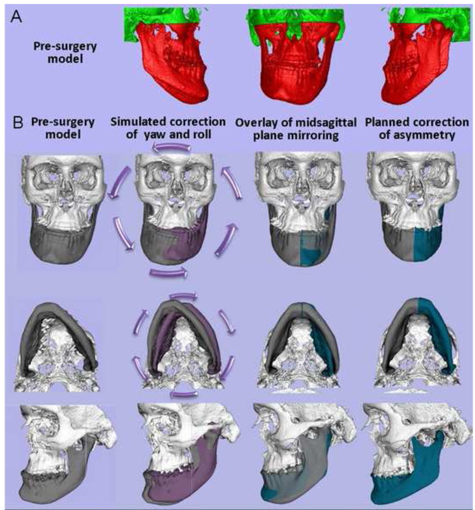
Figure 10. Clinical case 2.
Application of the techniques validated in this study to aid surgical treatment planning. Presurgical 3D diagnosis of a patient with right hemi-mandibular hypertrophy that was not included in the validation study. (A) Patient’s pre-surgery virtual surface models. The mandible and maxilla are labeled in red and cranial base is labeled in green. Note that the patient’s hypertrophic left condyle did not articulate inside the articular fossa in centric occlusion. His left condyle articulated with the zygomatic arch in centric occlusion before projecting to maximum intercuspation. The 3D virtual diagnosis did not move the condyle out of the fossa. The actual surgery as shown in Figure 11 did not change his articulation on left side as he had a working condyle in that abnormal anatomical location. (B) Diagnostic steps where mandibular 3D rotational displacements are virtually corrected prior to the use of mirroring techniques. Such procedures allowed the assessment of true left and right shape differences. The white and gray models display the patient actual facial structures. The purple models are the virtually simulated correction of yaw and roll. In the virtual simulation, the mandible was reoriented with the left condyle as the center of rotation before mirroring to correct asymmetrical mandibular yaw and roll, in an attempt to place the chin in a clinically acceptable location while preserving the facial width. The mandible was rotated 6 degrees counter-clock wise in the frontal plane and 5 degrees clock-wise in the axial plane. After the virtual correction of yaw and roll of the mandible, the real model is the mirror model using the midsagittal plane. Note the overlays between the purple/gray and green/gray models to help plan surgical displacements.

