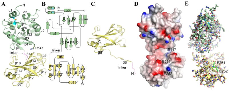
Figure 4.
X-ray crystal structure of TcpF. (A) Full-length TcpF is a bilobed structure comprised of an N-terminal domain (NTD, green) and a C-terminal domain (CTD, yellow) joined by a linker (residues 186–189, magenta). (B) Topology diagram of TcpF. (C) Crystal structure of TcpF-CTD. In the absence of the NTD, the linker segment enters the CTD at residue 198. (D) Space-filling representation of TcpF showing the negatively-charged cleft between the NTD and CTD. The protein is colored according to electrostatic potential, calculated using DELPHI 49, where red represents negative charge, blue is positive and white is uncharged (scale −7 kT to +7 kT). (E) TcpF critical binding residues Glu251 and Glu252 for mAb13 recognition. Glu251 and Glu252 (carbon atoms are colored bright green) lie at the lip of the cleft in the C-terminal domain.

