Figure 3.

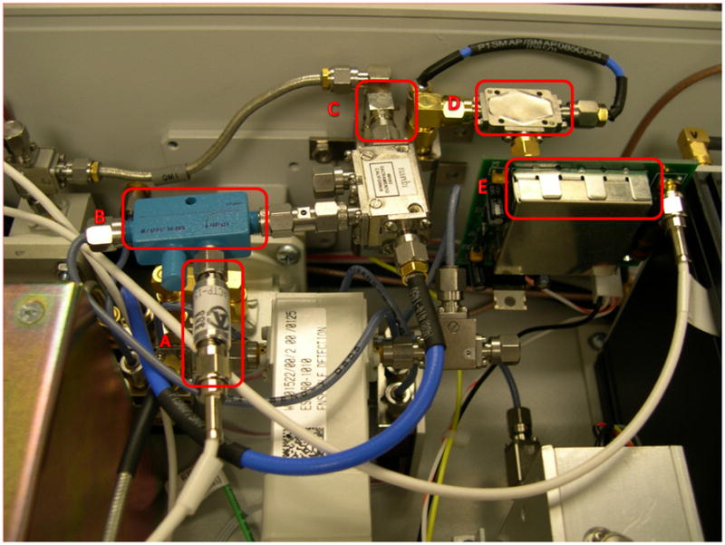
Photograph of the pulsing circuit installed in a Bruker X-band bridge. The crystal detector (A), directional coupler (B), transfer switch (C), microwave mixer (D) and circuit card (E) are shown.

Photograph of the pulsing circuit installed in a Bruker X-band bridge. The crystal detector (A), directional coupler (B), transfer switch (C), microwave mixer (D) and circuit card (E) are shown.