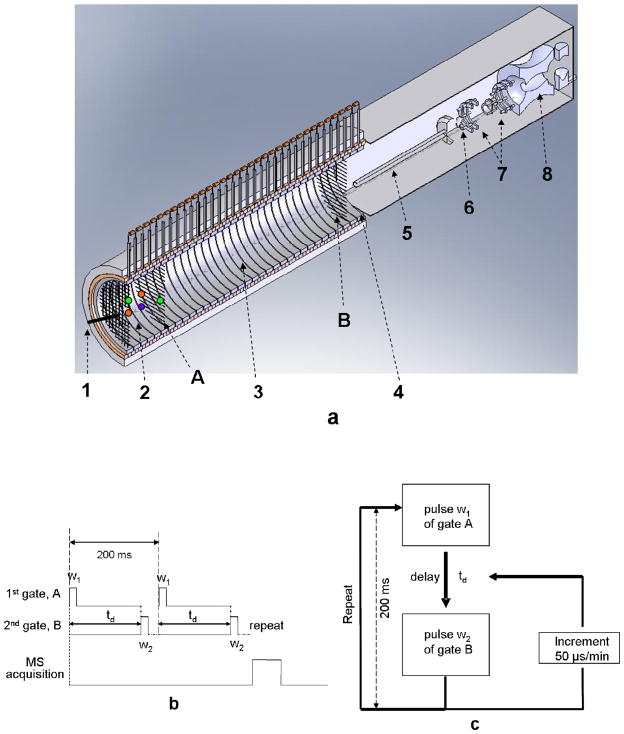
Figure 1.
Schematics of the electrospray ionization, ambient pressure two-gate ion mobility-quadrupole ion trap mass spectrometer and timing sequence diagrams. a. The instrument setup. 1. electrospray tip; 2. desolvation region; 3. drift region; 4. interface region. 5. heated capillary; 6. skimmer; 7. octapole; 8. quadrupole ion trap. Ions were introduced into the desolvation region by the electrospray ionization process. They entered the drift region once gate A was pulsed open. Gate B was triggered to open by gate A after certain delay of time td to allow ions fly through the drift region. b. Timing sequence of the mobility selected mode. The pulse train signal in high position (gate open) was 5 V. When in low position (gate close), no voltage was applied. Gate A was typically opened for 0.5 ms, and the second gate either opened over a wide window period to initially find approximate regions of precursor ion abundance after a selected delay, or set for a narrow period just wide enough to cover a single ion’s peak width after a drift period td. Multiple ion mobility runs could be used to repetitively fill the trap, and mass spectra that were accumulated using the trap could also be signal averaged. c. Timing sequence of the mobility-scanning mode. A delay time td in milliseconds (i.e. 39 ms) was preset between the pulses of gate A and B. Multiple incremented delays could be performed (i.e. 50 μsec increments/min), keeping the second gate-open time constant (pulse width w2 μsec) to scan drift-time regions of interest (i.e. 39~42 ms). Every ion mobility experiment in this scanning mode was repeated every 200 ms.

