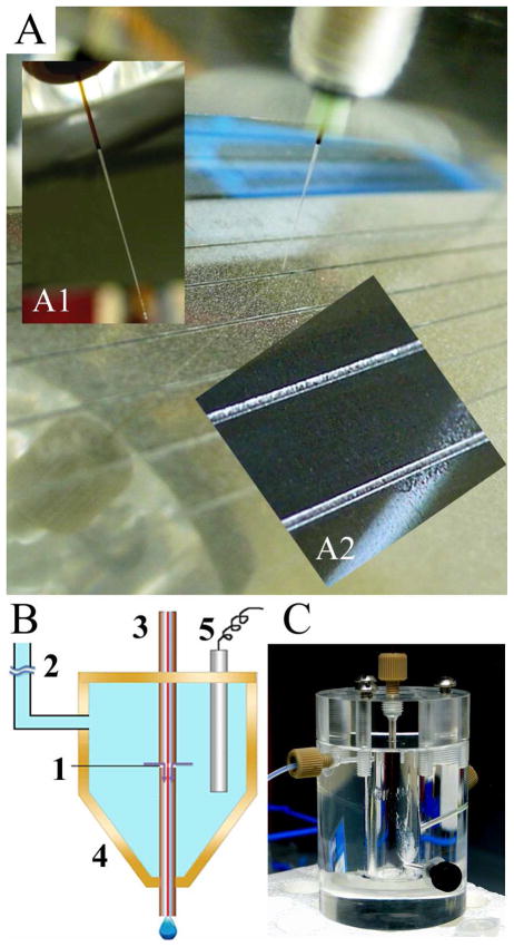
Figure 1.
(A) Photograph of the MALDI-MS target plate with grooves (250 μm wide, 100 μm deep) and sprayed DHB matrix. The distal end of the capillary slides in the grooves, bearing an angle (60°) with the target plate. (Inset A1) Photograph of the distal end of the etched capillary, the outside diameter was narrowed to ~150 μm for obtaining increased flexibility to fit in the groove. (Inset A2) Close-up photograph showing grooves and the matrix distribution. (B) Schematic drawing of the off-line CE-MALDI-MSI interface with an open fracture on the end section of the capillary (~3 μm gap) for ions to exchange and for cathodic background electrolyte (BGE) to enter the deposition section. 1. Open fracture; 2. Buffer line to hydrostatic height; 3. Separation capillary; 4. Buffer reservoir; 5. Pt cathode. (C) Photograph of the BGE buffer reservoir assembly.

