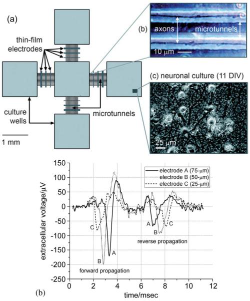
Fig. 4.
Microtunnel electrode array. (a) Schematic diagram showing four culture wells, each connected by a series of microtunnels to a central well. There are stimulating/recording electrodes in the wells and crossing the tunnels. The tunnels are 3 μm high by 10 μm wide by 750 μm long. (b) The amplitudes of the axonal potentials are much higher than normal due to the restricted and hence high resistance space in which the axons grow. Direction of propagation can be determined by the temporal order in which spikes occur on the electrodes place along the tunnels. (Reproduced by permission of The Royal Society of Chemistry (RSC) [47].)

