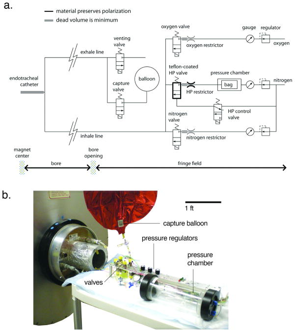
Figure 1.
a) Schematic of the ventilator. From the upper right corner of the schematic: oxygen flows through a regulator, a pressure gauge, then a flow restrictor. Its delivery to the animal is controlled by the oxygen valve. The nitrogen line operates similarly. Hyperpolarized gas is delivered from a Tedlar bag which resides in a rigid chamber that is pressurized by N2. The valve, restrictor, and tubing that handle HP gas are built from polarization-preserving materials, as indicated by the bold line. All gases are combined at the valve outputs and directed through the inhale line to the endotracheal tube. After inspiration and a brief breath-hold for imaging, gases are expelled by opening the venting valve (normal breathing) or capture valve (HP gas breathing). Note: tubing represented by a triple line indicates that the dead volume must be minimized. b) the ventilator and all the valves are positioned in the ~0.1 T fringe field of the 2 Tesla magnet during imaging. One-meter-long lines direct the breathing mixture towards the animal at the center of the magnet, or recollect the exhale mixture

