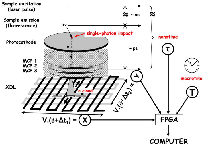
Fig. 1.
Principle of the H33D detector. Each photon is converted by the photocathode into a photoelectron amplified ~107 times by the MCP stack. The time interval between the pulse generated at the back of the MCP and the laser pulse (nanotime τ) is measured by a TDC. The electron cloud is collected by a cross-delay line anode and a timing electronics module converts the differences in charge arrival time at both ends of the delay lines into position information (X, Y). A laser pulse counter built in the readout electronics provides a 4th coordinate, the macrotime T, which is associated with the 3 other coordinates by a dedicated field-programmable gate array (FPGA), before being sent asynchronously to the computer. δ: fixed time delay. V: velocity factor proportional to the actual anode signal propagation velocity. From ref. 1.

