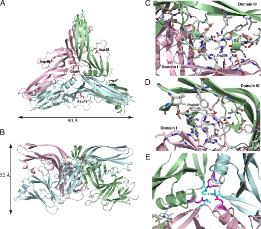
FIGURE 2.
Trimeric structure of CPE. A, view from the top of the trimer and parallel to the 3-fold axis. B, view perpendicular to the 3-fold axis. Each monomer is defined by a different color, blue, green, or pink. Asp48 is rendered as red sticks in each monomer. C–E, views of the interface between monomers. Residues directly involved in contact between the monomers are shown as stick models. The calculations of interfaces between monomers were performed by PISA. C and D, dimeric interface between domains I and III. E, trimeric interfacing center of CPE. Glu94 and Glu110 of each monomer are featured as magenta and light blue sticks, respectively.

