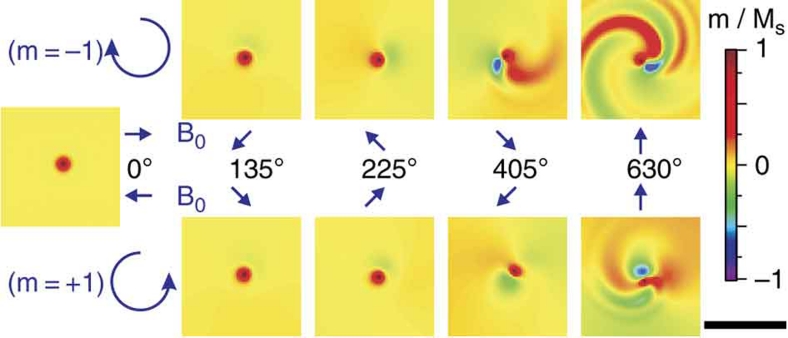
Figure 3. Snapshots during spin-wave excitation before vortex core reversal.
The frames show the time evolution of the out-of-plane magnetization for a vortex up during the application of in-plane rotating magnetic fields. Only the inner part of the sample is shown. The size of the black bar corresponds to a length of 200 nm. The left frame corresponds to the relaxed ground state (phase angle 0°). The two rows oppose counter rotating modes at a frequency of 5.0 GHz for the (m=−1) mode and 6.2 GHz for the (m=+1) mode at the same azimuthal angle of the external field. The blue arrows in the middle indicate this angle for the corresponding frame.

