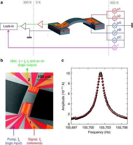
Figure 1. The electromechanical parametric resonator.
(a) A schematic of the experimental setup where the mechanical resonator is in the geometry of a doubly clamped beam (grey) with a length, width and thickness of 260, 84, and 1.35 μm, respectively, and it hosts an out-of-plane oscillation mode. The mechanical oscillator has Schottky Au-electrodes (orange) located above both clamping points, below which a 2DEG is located (red). Application of a.c. bias to either the 2DEG or the Au-electrodes can trigger both harmonic and parametric resonances where the mechanical motion is monitored by detecting in either a lock-in amplifier or a spectrum analyser the motion-induced piezovoltage, which is amplified by an on-chip amplifier (red triangle) and a room temperature transimpedance amplifier (black triangle). In all cases, the signals s1 and s2 are applied to the large Au-electrode with a 50 μVrms actuation amplitude and the pumps pA, pB and pC are applied to the 2DEG with 40 mVrms actuation amplitude where the reference r is used for the lock-in measurements. (b) A false-colour scanning electron microscopic image of the electromechanical resonator where the pump (logic input), signal excitation (to functionalize logic operations) and the idler (logic output) are marked. (c) The electromechanical resonance (dots) measured via the lock-in amplifier and fitted with a harmonic oscillator response (line).

