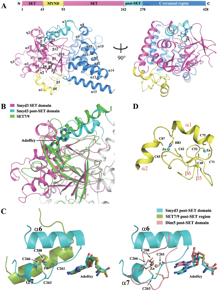
Figure 1.
Structure of the Smyd3–AdoHcy complex. (A) Overall structure of the Smyd3–AdoHcy complex. Top: a schematic representation of the full-length Smyd3 with the N-terminal SET domain (residues 1–43 and 94–242), the MYND domain (residues 44–93), the post-SET domain (residues 243–270), and the C-terminal region (residues 271–428) colored in magenta, yellow, cyan and blue, respectively. Bottom: two views of the overall structure of the Smyd3–AdoHcy complex. The domains are colored accordingly and the secondary structure elements are marked. The cofactor product AdoHcy is shown with a ball-and-stick model and colored in cyan. (B) Structural comparison of the SET and post-SET domains of Smyd3 with the equivalent regions of SET7/9 (PDB code 1O9S). Superposition of the Smyd3 and Set7/9 structures was performed based on the core region of the SET domain. SET7/9 is colored in green, and the color coding for Smyd3 is the same as in Figure 1A. The cofactors are shown with ball-and-stick models and colored accordingly. (C) Comparison of the Zn2+-binding site in the catalytic core of Smyd3 with the equivalent regions of SET7/9 (left panel) and Dim 5 (PDB code 1PEG, right panel). The post-SET regions of Smyd3, SET7/9 and Dim5 are shown with ribbon representations and colored in cyan, green and wheat, respectively. The side chains of the involved Cys residues and the bound cofactors are shown with ball-and-stick models and colored accordingly. The Zn2+ ions are shown with sphere models and colored accordingly. The secondary structure elements and the involved Cys residues in Smyd3 are labeled. (D) Zinc-binding sites in the MYND domain. The MYND domain (yellow) is characterized by a C6HC zinc chelating motif. The side chains of the Cys and His residues chelating the two Zn2+ ions are shown with ball-and-stick models. The Zn2+ ions are shown with sphere models. The secondary structure elements and the involved residues are labeled.

