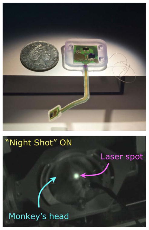
Fig. 8.
Upper trace: Full photographic image of the implantable microsystem (displayed as though viewed from the direction of the skull/brain). The cortical front end’s flexibility is shown by gravity pull (for realistic animation of the flexibility of the cortical–cranial tether, see [57] at www.braingate2.org/sensors.asp). The ground reference wire is visible, but the receiving planar inductive coil on the backside of the cranial module is not. The polymer encapsulant shows holes which are presently used to fix the cranial module onto the skull via Ti-screws to prevent motion from impact by a monkey in its cage. Lower trace: Transmitted IR laser from the top of a monkey’s head (restrained), with an implanted microsystem under operation, imaged by a night vision camera.

