
Fig. 9.
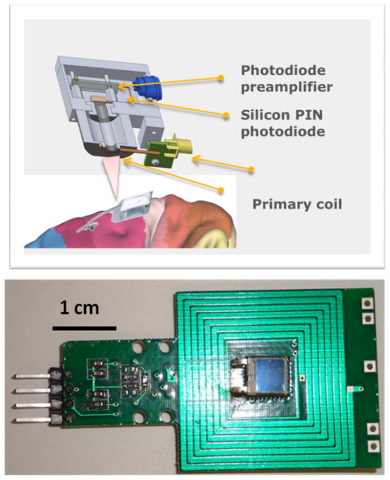
Upper trace: Schematic of the external-to-head-unit in an exploded view, displaying the IR photoreceiver and RF inductive power coils, respectively. Lower trace: a photograph of the PCB layout of the unit, where the primary RF coil and the photodiode are “co-centric,” together with the latter’s preamplifier circuit [59].