
Figure 1.
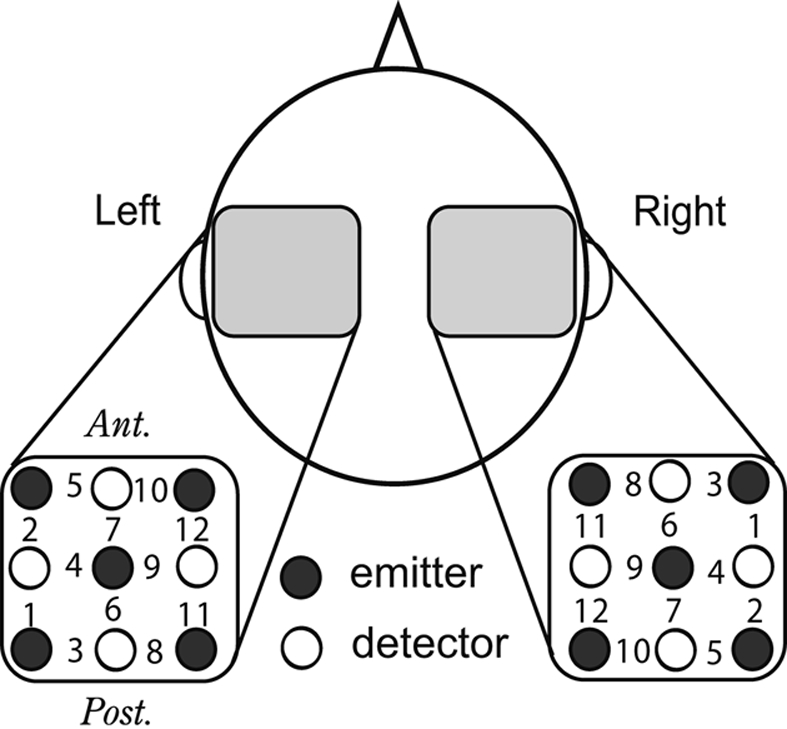
Arrangement of NIRS recording probes. A schematic top view of the head shows that five emission and four detection probes were placed on the temporal scalp with a thermoplastic shell in a 3 × 3 square lattice, 3 cm apart from the nearest others, which constituted 12 recording sites on each side. The light incident probes are represented by filled circles; the detection probes, by open circles; measurement channels, by numerals.