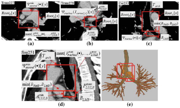
Fig. 4.
Example of station 4, as computed automatically by the LNSM. The red rectangular boxes indicate the location of the station in each view. Labels indicate the landmarks defining the limits of the two cuboids defining station 4, per Table 3. Dimensions of 4S: 65 mm × 70 mm × 63 mm; 4I: 37 mm × 31 mm × 13 mm. a Portion of 2D x–y transverse-plane section I (·, ·, 227) passing through cuboid 4S. b Portion of 2D x–y transverse-plane section I (·, ·, 279) passing through cuboid 4IR. c Portion of 2D x–z coronal-plane section I (·, 233, ·) passing through both adjoining cuboids of station 4. d Portion of 2D y–z sagittal-plane section I (251, ·, ·) passing through both adjoining cuboids of station 4. e 3D surface rendering of station 4 with respect to the airway tree, with complete set of lymph nodes depicted in orange per TNM system convention (Fig. 1)

