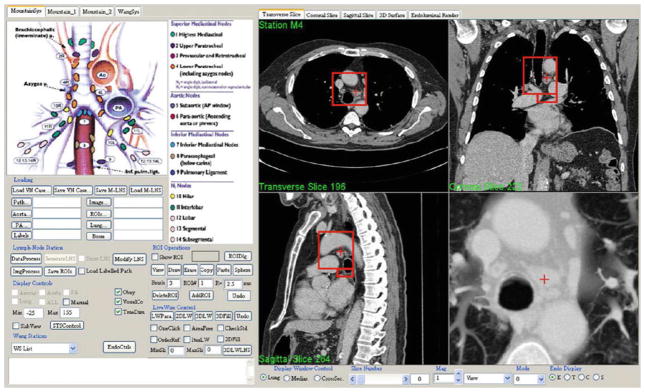
Fig. 7.
Top-level form of LNSM GUI. The user selects a desired computed TNM station by pointing to the station on the TNM system legend (top left center). Many controls exist for interacting with the stations and selecting/defining lymph nodes of interest (bottom left). The right side of the GUI is dedicated to visualization, which generally depicts four linked interactive views. In this example, transverse section z = 196, coronal section x = 222, sagittal section y = 264, and a magnified thin slab view of station 4 appears. The red boxes indicate the 3D location of the station on the presented sections, while the red crosses indicate the current 3D viewing position

