
Figure 7. Modelling analyses of PHPLC-GFP fluorescence intensity induced by stimulation of Ci-VSP phosphatase activity.
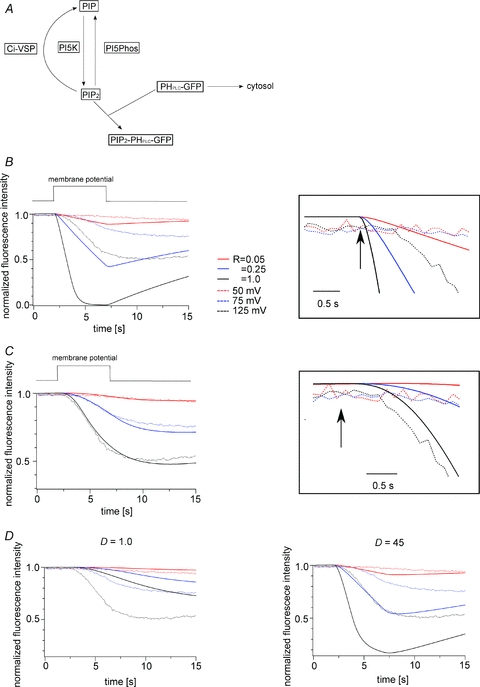
A, scheme of the modelling. B, result obtained in the model when diffusion of PHPLC-GFP was not taken into account. Dotted and continuous lines indicate the experimental data and the modelling results, respectively. The right panel is a magnified view of the decay after the onset of depolarization (arrow). C, result obtained in the model when diffusion of PHPLC-GFP was taken into account. The experimental data and Ci-VSP density are the same as in B. [Ci-VSP] = 21,894 μm−1, D = 4.5 μm2 s−1. Right panel is a magnified view. D, fitting of the PHPLC-GFP fluorescence data while changing the value of diffusion coefficient (D). The diffusion coefficients were set to 1.0 μm2 s−1 for the left panel and 45 μm2 s−1 for the right panel. Dotted and continuous lines indicate the experimental data shown in B and the results estimated from the model, respectively. The colour code is the same as in B.