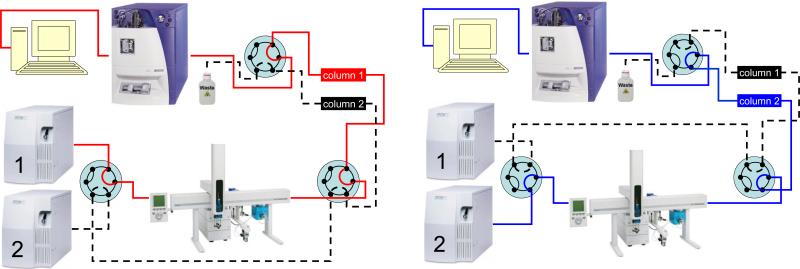
Figure 1.
LC system with two parallel flow channels used for multiple consecutive sample injections. The left panel represents the state where 6-port 2-position valves are switched in Position 1. Sample injection and LC separation are performed on Column 1; the analytical channel is marked in red. The right panel represents the state where the valves are in Position 2, with sample injection and separation being performed on Column 2; the analytical channel is marked in blue.

