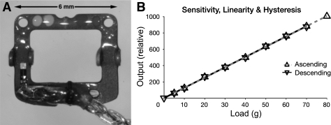
Fig. 1.
Muscle force transducer (MFT). A: finished device (“left” orientation). A stainless steel frame carries two semiconductor strain gauges (SGs; one visible near the bottom left and the other on the underside of the opposite beam, near the bottom right) wired as the arms of a Wheatstone bridge. The device is encapsulated in epoxy resin and Parylene-C and is attached by pushing a pin (not shown) through holes in the four upward-bent bearing tabs and under the muscle and held in the desired orientation (see Fig. 2) with nonabsorbable sutures passed through the muscle margins and the holes visible in the top left and right corners. B: typical MFT calibration. Bench calibration with ascending and descending weights showed the devices to be linear (r2 > 0.999) and without measurable hysteresis. The device sensitivity is overwhelmingly determined by the stiffness of the steel frame, so individual MFTs differed little, and the tissue that grows around implanted devices is unlikely to affect sensitivity.

