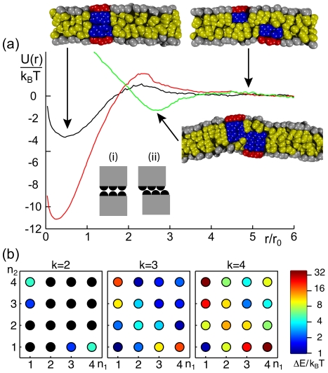
Figure 6. Dimerization of two peripheral membrane proteins in opposing leaflets.
(a) Representative potentials of mean force,  , of two PMPs (
 ) residing in opposing leaflets. For combinations of sufficiently short proteins (
 , black curve;
  , red curve) the minimum of
  emerges at vanishing distances. For
  a slight increase of
  is observed as a result of the PMPs' construction via finite beads, i.e. configuration (i) is energetically less favorable than arrangement (ii). For longer proteins (
 , green curve), a side-by-side arrangement of PMPs is observed, and the minimum of
  hence is shifted to larger distances. Representative snapshots indicate the discussed arrangements; hydrophilic and hydrophobic groups are shown in red/grey and blue/yellow, respectively. (b) Phase diagram for the dimerization ability when changing the membrane anchor lengths
  and
and  of a pair of PMPs. Color-coded values of
  indicate the binding strength. Please note the logarithmic scale of the color-coding; values with
  are marked in black.

