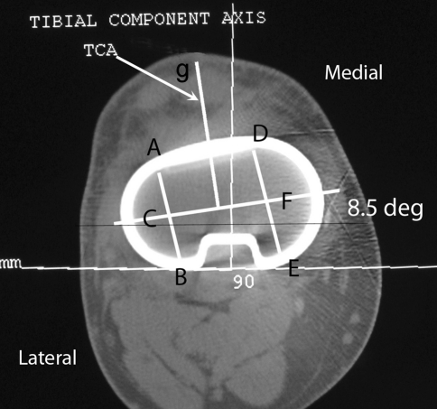
Fig. 4.
A modification of the technique to assess the rotational position of asymmetric tibial components is shown. Lines AB and DE cross the lateral and medial hemiplateau respectively. Both are bisected. A third line, CF, connects the centers of each hemiplateau and defines the flexion axis for an asymmetric component. The line at right angles to the flexion axis (indicated by the arrow and terminating at g), defines the TCA for an asymmetric component. In this case the TCA was corrected by 8.5%.

