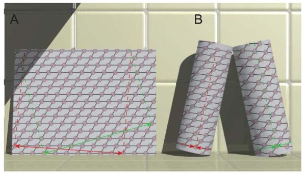
Figure 2.
Relationship between a planar 2D lattice and a helical assembly. (A) The 2D lattice is characterized by a regular array of points. An infinite variety of lines can be drawn through these points and each set of lines can be assigned a Miller index (h,k). For example, the black lines shown here could be assigned to the (1,0) and (0,1) directions. Two circumferential vectors are shown in green and red and these can be used to generate two unique helical structures shown in panel B. The dashed red and green lines are parallel to the z axes in the resulting helical structures. (B) Helical lattices result from superimposing lattice points on either end of the circumferential vectors shown in panel A. Each set of lines through the 2D lattice are transformed into a family of helices. The start number (n) of each helix corresponds to the number of lines that cross the circumferential vector. The red circumferential vector produces helices with n=1 and n=10. The green circumferential vector produces helices with n=−4 and n=8. For a left-handed helix, n<0.

